
SimulIDE Knowledge Base
– SUBCIRCUITS –
Subcircuits
These components are just circuits “packed” inside a package.
There are already many subcircuits included in the default installation, for example all components of the 74 or CD series.
All the files for subcircuits in the default installation are in “data” folder.
You can have a look to the files of these components to get an idea of how they are implemented.
There are several types of subcircuits, but we can group them into 2 categories:
An example of ICs already included in SimulIDE are all 74 and CD series.
And examples of Boards are Arduinos, and components in “Led displays” and “Tools” categories in the component list.
Creating Subcircuits
Creating a subcircuit involves these steps:
- Creating Package File.
- Creating circuit file.
- Creating component folder with all files.
- Add to component list
Integrated Circuits:
These are just circuits in a package, similar to real ICs.
Creating circuit file.
To use a circuit in a subcircuit just connect your circuit to Tunnels:  .
.
Then Set the names of these Tunnels the same as the Pin Ids in the Packages (not the Pin names).
Save this circuit and use this .sim1 file as circuit file.
You can do all in one Circuit, as in the image below, with both Chip and Logic Symbol packages and circuit.
This is not always required, but this way you can see and edit the package files and circuit in the same place:

Boards:
Boards are subcircuits that have some graphical elements, often used for interaction, for example switches, potentiometers, displays, etc.
Creating a board is similar to any other subcircuit, the first step is creating the circuit and add tunnels to connect to Package pins.
The only difference is about graphical components.
These components need to be placed is a specific position inside the package, so it requires an additional step:
Placing Graphical Components:
When a package is configured as type “Board” a new item Board Mode appears in the context menu.
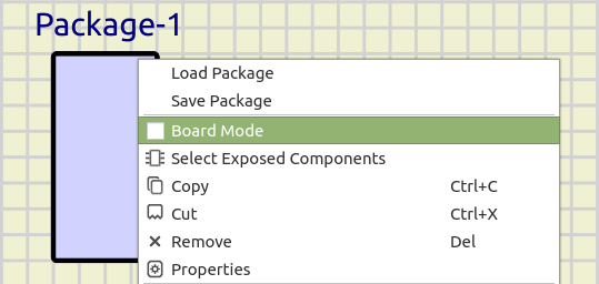
When you select Board Mode, all the non graphical components and wires disappear and the graphical components remain.
Now you can place all graphical components into the board.
Graphical components must be completely within the board rectangle.
When all components are placed right-click and deselect Board Mode to return to the normal circuit view.
Don’t forget to save package file and circuit.
Exposed Components:
Sometimes you want to access some functionality of some of the components in a subcircuit, for example in an Arduino board you want to be able to load firmware into the internal ATmega328.
For this you can use the option Select Exposed Components in package’s context menu. When you click on it the cursor changes to  And you can select/deselect components.
“Exposed” components are highlighted in yellow:

To return to normal mode just click in any empty space or right-click.
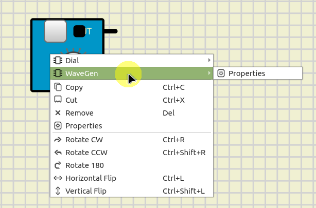
Later, when you use this subcircuit in your circuits, you will be able to access exposed components from the subcircuit’s context menu:
Modules:
Modules are an special type of Board that can be stacked on top of Boards or other Modules. In a similar way to Shields but with more freedom and in a more general way.
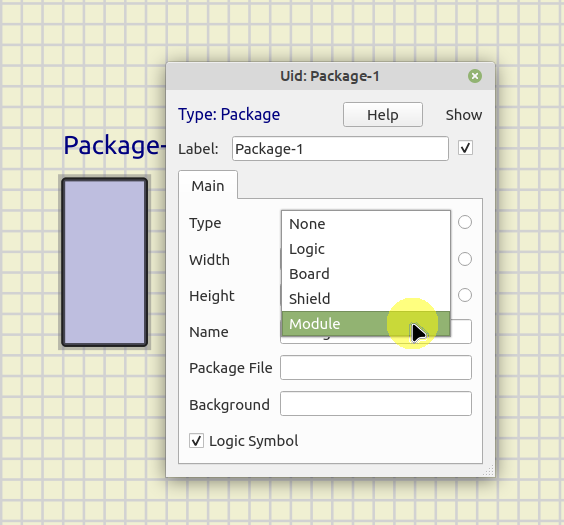
To create a Module, select “Module” in Package type:
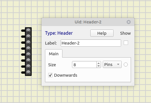
Modules are connected using Sockets and Headers.
The Board or Module below should use a Socket and the Module to be stacked on top should use a Header pointing down:
For example in this case “board2” can be stacked on top of “board1” and “board1” on top of “board0”:
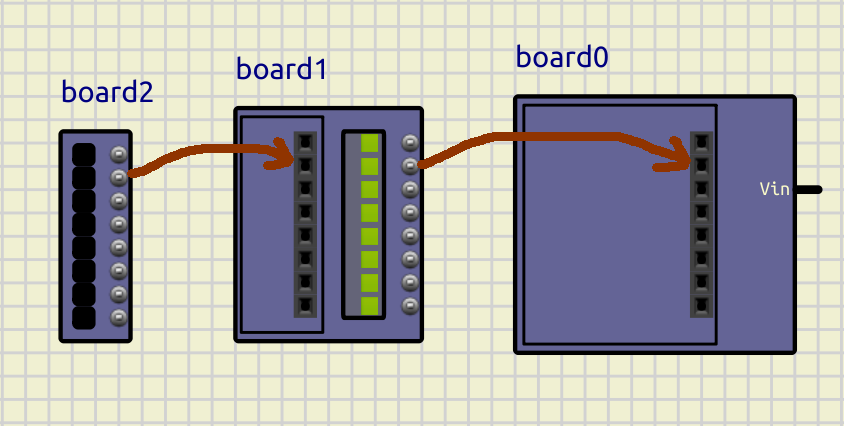
Just by placing the Header aligned on top of a Socket it will connect and the simulation will work.
To get a Module “attached” to a Board or another Module, Right-Click on it and select “Attach”. Then the Module will move with the board below it
To “free” the Module again, Right-Click on it and select “Detach”.
Resources:
Videos:
#tutorial