
SimulIDE Knowledge Base – LOGIC ANALYZER
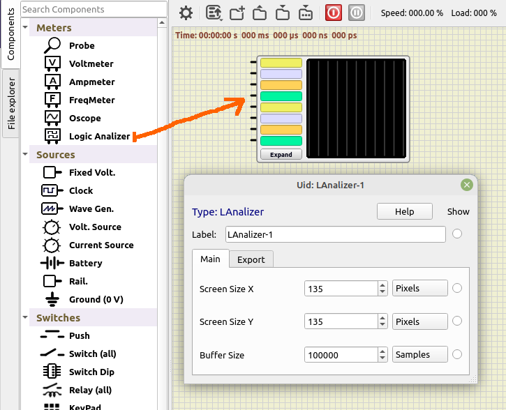
Logic Analyzer has 8 channels identified with different colors for each channel.
You can connect inputs to wires or enter a tunnel name in the corresponding box.
Connecting the inputs and running the simulation you will see the wave forms:

Properties:
Opening the properties (double-click) you can configure:
- Screen Size X: screen width when not expanded (default: 135).
- Screen Size Y: screen height when not expanded (default: 135).
- Buffer Size: number of samples retained in memory (default: 100000).
We will have a look at the “Export” group of properties later.
Expanded mode:
Click in “Expand” button to get a window with a more detailed view and all the controls.
This floating window is resizable and you can close it like any other window:
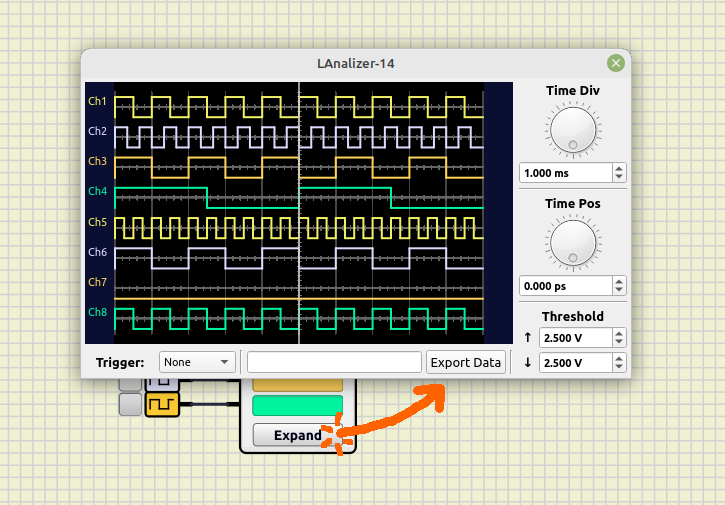
Controls:
From top to bottom, you can find the following controls:
Time controls:
With these you can zoom-in or zoom-out in time (for all channels) and set the horizontal position of each channel.
- Time Div: size of one horizontal division in the screen.
- Time Pos: relative position in time.
You can edit time values with the dial, or set a value in the correspondig box.
You can enter a multiplier after the value in value boxes, for example write: “10m” + Enter, to set 10 miliseconds
You can also use the mouse in Logic Analyzer screen:
- Mouse wheel to zoom in/out.
- Left-Click and move to change position.
- Cursor shows time value.
Threshold:
Voltage used to detect logic states and triggers.
- ↑: Low to High threshold in Volts.
- ↓: High to Low threshold in Volts.
Trigger:
You can select any channel as a trigger source.
Or you can select “Condition” trigger to pause simulation when a condition occurs.
And enter an expression in the white box at the right.
Condition trigger works like a “one shot” trigger, but in addition it pauses the simulation, and you can zoom in/out, move in time, etc.
Conditions are expressions like this:.
Ch1R to pause in every channel 1 Rising egde.
Ch2F to pause in every channel 2 Falling edge.
Available states are: L, R, H, F, for Low, Rising, High, Falling.
You can use logic expressions like:
( ( (Ch1R & Ch2H) | (Ch4L & Ch3H & Ch2F) ) & Ch6H ) | Ch8R
Conditions are case insensitive, Ch1R, cH1r or CH1r are valid.
Export Data:
You can export the data in the screen by clicking this button.
This will open a file dialog, to choose an Vcd file to save the data.
The “Export” tab in the properties dialog is related to this feature:

- Base Time Step: time step used for the vcd file.
- Export at pause: automatically export vcd file at simulation pause (Condition Trigger).
You can combine Condition Trigger, Export Data and a program like Pulseview to do protocol decoding.
Resources:
- Video (english):
- Video (spanish): Analizador Lógico SimulIDE 1.0.0