SimulIDE Knowledge Base
– COMPONENT LIST –

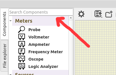
Component list is in the left panel under the tab “Components”.
It is organized in categories and subcategories. All categories are expandable/collapsablewith the little arrow at the left of the category name.
Expanded/Collapsed state is saved and restored, so it will look the same next session.

It is also possible to hide categories or single components from the list.
This way you can create a simpler Component List if you will only use some of them, for example you can create a list for only Logic Components.
To do this, Right-Click on any part of the list and select “Manage Components“.
A widget will open where you can select which categories/Components will be visible.

You can search components using the search box at the top of the list.
Just type some text and hit enter:


List of Components by category:


Meters

Logic and voltage probe.
Hover or connect to Wires or Pins to get voltage.

As logic probe: - Orange = High State. - Blue = Low State


Properties:

Property: (default value)

  • Show Voltage: (yes)
    Show voltage label.

  • Threshold: (2.5 V)
    Digital threshold to determine High/Low states.


Voltage meter with output pin.


Pins:

  • Red Pin: Positive.
  • Black Pin: Negative.
  • Right Pin: Output reading as voltage (updates at Circuit FPS)

Current meter with output pin.


Pins:

  • Red Pin: Positive.
  • Black Pin: Negative.
  • Right Pin: Output reading as voltage (updates at Circuit FPS)

Frequency meter.


Properties:

Property: (default value)

  • Filter: (0.1. V)
    Filter out any voltage change below this value.

Oscilloscope with 4 channels identified with different colors and frequency indicators for each channel.

There is one input pin per channel and one for reference voltage (last one besides Expand button).
You can connect inputs to wires or enter a tunnel name in the corresponding box.
Connecting the inputs and running the simulation you will see the wave forms.


Properties:

Property: (default value)

  • Screen Size X: (135)
    Screen width when not expanded.

  • Screen Size Y: (135)
    Screen height when not expanded.

  • Buffer Size: (600000)
    Number of samples retained in memory.

  • Connect to ground: (true)
    Add an impedance to ground for each input.

  • Impedance: (10 MΩ)
    Value of impedance to ground If connected).


Expanded mode:

Click in “Expand” button to get a window with a more detailed view and all the controls.
This floating window is resizable and you can close it like any other window.


Resources:

Tutorial:

Logic Analyzer has 8 channels identified with different colors for each channel.

You can connect inputs to wires or enter a tunnel name in the corresponding box.
Connecting the inputs and running the simulation you will see the wave forms.


Properties:

Property: (default value)

Main:

  • Screen Size X: (135).
    Screen width when not expanded.

  • Screen Size Y: (135).
    Screen height when not expanded.

  • Buffer Size: (100000).
    Number of samples retained in memory .

Export:

  • Base Time Step: (100 ps)
    Base time used in VCD file.

  • Export at pause: (false)
    Export to VCD file at Simulation pause.


Expanded mode:

Click in “Expand” button to get a window with a more detailed view and all the controls.
This floating window is resizable and you can close it like any other window.


Resources:

Tutorial:

Sources

Simple voltage source.

Turn On/Off with the letf button.


Properties:

Property: (default value)

  • Voltage: (5 V)
    Output voltage.

Clock source.

Turn On/Off with the letf button.


Properties:

Property: (default value)

  • Voltage: (5 V)
    Set output voltage.

  • Frequency: (1000 Hz)
    Set output frequency.

  • Always On: (yes)
    Removes the button and keeps always active.


Wave generator.

Turn On/Off with the letf button.


Wave types:

sin.png Sine
saw.png Saw
tri.png Triangle
sqa.png Square
rnd.png Random
wav.png Wav


Properties:

Property: (default value)

Main:

  • Wave type: (Sine)
    Set output wave type.

  • Frequency: (1000 Hz)
    Set output frequency.

  • Phase shift: (0 º)
    Phase shift relative to wave start.

  • Quality: (100)
    Number of steps per cycle.

  • Duty: (50 %)
    Duty cicle.
    Not available for all types.

  • Always On: (yes)
    Removes the button and keeps always active.

Electric:

  • Bipolar: (false)
    If true, use 2 output pins.

  • Floating: (false)
    If true, output voltages are not refered to ground.
    Only visible is Bipolar is true.

  • Middle Voltage: (0 V)
    Central voltage of the wave.

  • Semi amplitude: (2.5 V)
    Half wave amplitude.


Resources:

Videos:

Variable Voltage Source.

Turn On/Off with the left button.
Adjust voltage using the dial (0 to max voltage).
Button shows voltage output at this moment.


Properties:

Property: (default value)

  • Current value: (0 V)
    Current voltage output.

  • Maximum Voltage: (5 V)
    Maximum voltage (positive or negative value).
    Must be > Minimum Voltage.

  • Minimum Voltage: (0 V) Minimum voltage (positive or negative value).
    Must be < Maximum Voltage.


Variable Current Source.

Turn On/Off with the left button.
Adjust current using the dial (0 to max current).
Button shows current output at this moment.


Properties:

Property: (default value)

  • Current value: (0 A)
    Current output at this moment.

  • Maximum Current: (1 A)
    Maximum current (must be a positive value).


Simple battery.


Properties:

Property: (default value)

  • Voltage: (5 V)
    Battery voltage.

  • Resistance: (0.001 Ω)
    Internal resistance.


Connection to voltage rail.
This is a simple voltage source.


Properties:

Property: (default value)

  • Voltage: (5 V)
    Rail voltage.

Connection to Ground.
This is a 0 V voltage source.


Switches

Configurable push button switch.


Properties:

Property: (default value)

  • Normally Closed: (no)
    Push to open (yes) or push to close (no).

  • Poles: (1)
    Number of poles controlled by this push button.

  • Key: ()
    Character shown in the button.
    Can be activated by keyboard in your PC.


Configurable 2 position switch.


Properties:

Property: (default value)

  • Normally Closed: (no)
    State with button not pushed.

  • Double Throw: (no)
    Yes: 2 throws per pole.
    No: 1 throw per pole.

  • Poles: (1)
    Number of poles controlled by this switch.

  • Key: ()
    Character shown in the button.
    Can be activated by keyboard in your PC.


Resizable set of switches.

Click on individual “buttons” to turn ON/OFF:


Properties:

Property: (default value)

  • Size: (8)
    Number of switches.

  • Exclusive: (false)
    Only onew Switch can be closed at a time.

  • Common Pin: (false)
    Connect all Switches to a common Pin.


Configurable electromagnetic relay.


Properties:

Property: (default value)

Main:

  • Normally Closed: (no)
    State with relay not active.

  • Double Throw: (no)
    Yes: 2 throws per pole.
    No: 1 throw per pole.

  • Poles: (1)
    Number of poles controlled by this relay.

Electric:

  • IOn: (0.02 A)
    Minimun current that activates the relay.

  • IOff: (0.01 A)
    Minimun current that holds the relay active.

Coil:

  • Inductance: (0.1 H)
    Coil inductance.

  • Resistance: (100 Ω)
    Coil resistance.

  • Reactive Step: (0 steps)
    Set custom Reactive step for this component.
    This value overrides general Simulation Settings.
    0 to use value set in Simulation Settings.


Configurable keypad.


Properties:

Property: (default value)

  • Rows: (4)
    Number of key rows.

  • Columns: (3)
    Number of key columns.

  • Key Labels: (123456789*0#)
    List of characters corresponding to each key.
    Left to right and top to bottom.


Passive / Resistors

Simple resistance.


Properties:

Property: (default value)

  • Resistance: (100 Ω)
    Resistance value.

Set of resistors in a DIP configuration.


Properties:

Property: (default value)

  • Resistance: (100 Ω)

  • Size: (8)
    Number of resistors.

  • Pullup: (no)
    Configure resistor Dip as pullups connecting directly to a voltage source.
    If true, it will disconnect and hide pins at the top.

  • Pullup Voltage: (5 V)
    Voltage to connect the resistors.
    Shown only if “Pullup” property is set.


Interactive potentiometer.

Use the dial to adjust the value.


Properties:

Property: (default value)

Main:

  • Resistance: (100 Ω)
    Maximum resistance with dial at top value.

  • Current Value: (0 Ω)
    Value determined by dial position.

Dial:

  • Slider: (false)
    true: Slider control.
    false: Knob control.

  • Scale: (1)
    Determines the size of the dial.


Interactive variable resistor.

Use the dial to adjust resistance.


Properties:

Property: (default value)

Main:

  • Minimum Resistance: (0 Ω)
    Resistance with dial at the left end.

  • Maximum Resistance: (1000 Ω)
    Resistance with dial at the right end.

  • Current Value: (0 Ω)
    Value determined by dial position.

  • Dial Step: (0 Ω)
    Minimum step when rotating the dial.
    0 to use default.

Dial:

  • Slider: (false)
    true: Slider control.
    false: Knob control.

  • Scale: (1)
    Determines the size of the dial.


Passive / Resistive Sensors

Interactive Light Dependent Resistor.

Use the dial to adjust luminance.


Properties:

Property: (default value)

Main:

  • Minimum Value: (0 Lux) Luminance with dial at the left end.

  • Maximum Value: (1000 Lux)
    Luminance with dial at the right end.

  • Current Value: (0 Lux)
    Value determined by dial position.

  • Dial Step: (0 Lux)
    Minimum step when rotating the dial.
    0 to use default.

Parameters:

  • Gamma: (0.8582)
    Determines resistance vs Lux slope.

  • R1: (127410 Ω)
    Resistance at 1 Lux.

Dial:

  • Slider: (false)
    true: Slider control.
    false: Knob control.

  • Scale: (1)
    Determines the size of the dial.

Interactive NTC thermistor.

Use the dial to adjust temperaturee.


Properties:

Property: (default value)

Main:

  • Minimum Value: (0 ºC)
    Temperature with dial at the left end.

  • Maximum Value: (200 ºC)
    Temperature with dial at the right end.

  • Current Value: (25 ºC)
    Value determined by dial position.

  • Dial Step: (0 ºC)
    Minimum step when rotating the dial.
    0 to use default.

Parameters:

  • B: (3455)
    β parameter.

  • R25: (10000 Ω)
    Resistance at 25 ºC.

Dial:

  • Slider: (false)
    true: Slider control.
    false: Knob control.

  • Scale: (1)
    Determines the size of the dial.


Interactive Resistance Temperature Detector.

Use the dial to adjust temperature.


Properties:

Property: (default value)

Main:

  • Minimum Value: (0 ºC)
    Temperature with dial at the left end.

  • Maximum Value: (200 ºC)
    Temperature with dial at the right end.

  • Current Value: (25 ºC)
    Value determined by dial position.

  • Dial Step: (0 ºC)
    Minimum step when rotating the dial.
    0 to use default.

Parameters:

  • R0: (100 Ω)
    Resistance at 0 ºC.

Dial:

  • Slider: (false)
    true: Slider control.
    false: Knob control.

  • Scale: (1)
    Determines the size of the dial.

Interactive Force Sensor.

Use the dial to adjust force.


Properties:

Property: (default value)

Main:

  • Minimum Value: (0 N)
    Force in Newtons with dial at the left end.

  • Maximum Value: (1000 N)
    Force in Newtons with dial at the right end.

  • Current Value: (0 N)
    Value determined by dial position.

  • Dial Step: (0 N)
    Minimum step when rotating the dial.
    0 to use default.

Parameters:

  • Ref. Temperature: (20 ºC)
    Reference Temperature.

  • Temperature: (20 ºC)
    Current Temperature.

Dial:

  • Slider: (false)
    true: Slider control.
    false: Knob control.

  • Scale: (1)
    Determines the size of the dial.


#Component

Passive / Reactive

Simple capacitor.


Properties:

Property: (default value)

  • Capacitance: (10 uF)

  • Resistance: (1e-6 Ω)
    Internal resistance.

  • Initial Voltage: (0 V)
    Voltage at simulation start (initial charge).

  • Reactive Step: (0 steps)
    Set custom Reactive step for this component.
    This value overrides general Simulation Settings.
    0 to use value set in Simulation Settings.


Resources:


Simple polarized capacitor.

This component will show a warning if polarity is wrong.

See Capacitor.


Simple inductor.

Blinks if reactive step is too long.


Properties:

Property: (default value)

  • Inductance: (1 H)

  • Resistance: (1e-6 Ω)
    Internal resistance.

  • Initial Current: (0 A)
    Current at simulation start (initial charge).

  • Reactive Step: (0 steps)
    Set custom Reactive step for this component.
    This value overrides general Simulation Settings.
    0 to use value set in Simulation Settings.


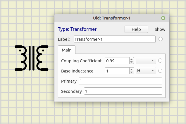
Configurable transformer.

This transformer is highly configurable, allowing users to set up as many coils as needed on each side.
It’s even possible to use coils exclusively on one side.

The term “Primary” refers to the left side, while “Secondary” refers to the right side.
However, any coil can function as the primary coil within the transformer.


Properties:

Property: (default value)

  • Coupling Coefficient: (0.99)

  • Base Inductance: (1 H)
    Base inductance for all coils (refer to the coil descriptions below)

  • Primary: (1)
    Description of coils in the left side (refer to the coil descriptions below).

  • Secondary: (1)
    Description of coils at the right side (refer to the coil descriptions below).


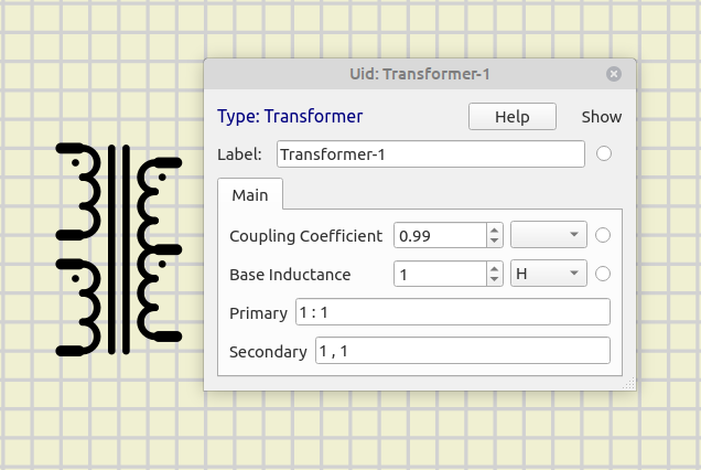
Description of coils:

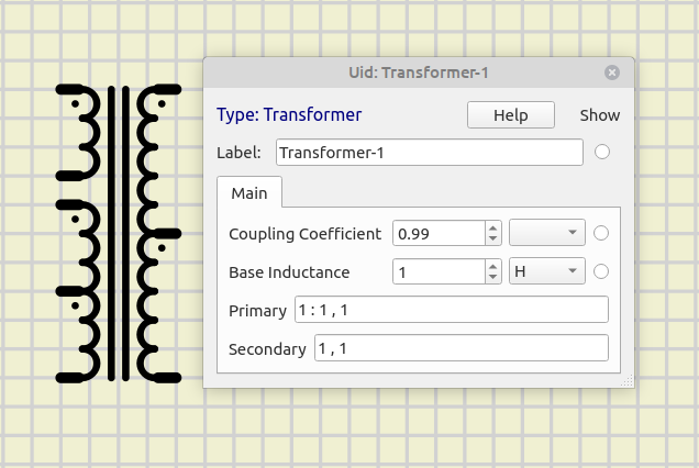
Coils are defined by values separated by “:” or “,
Separator “:” separates independent coils or groups of coils.
Separator “,” separates interconnected coils within a group.

Each value represents the voltage relation for one coil.
For example, using 1 for the primary coil and 2 for the secondary coil results in a 2x voltage at the secondary.
Or 1 for the primary coil and 0.5 for the secondary coil results in half the voltage at the secondary.

A negative value changes the direction of the coil (identified by the dot).

The coil inductance is calculated as follows:
Coil inductance = Base Inductance x value x value.

For instance, with a Base Inductance of 10 H and coils with values 1 and 3, the inductances will be:
Coil-1: L1 = 10 x 1 x 1 = 10 H
Coil-2: L2 = 10 x 3 x 3 = 90 H

You can use the number of turns for these values.
To do this you need to know the number of turns and Inductance of one of the coils, usually the primary coil. And use this formula:

Base Inductance =  L / N^2

Where L is the inductance of that coil and N the number of turns.


Some examples:

trafo0.png trafo1.png trafo2.png trafo3.png


Resources:


Active / Rectifiers

Configurable diode.

Blinks if maximum current is exceeded.


Properties:

Property: (default value)

Main:

  • Model: (Diode Default)
    Diode model determined by set of parameters.
    Add new models at file: data/diodes.model

Electric:

  • Fordward Voltage: (0.634767 V)
    Voltage drop when fordward biased.

  • Max Current: (1 A)
    Maximum current (it will blink if exeeded).

  • Resistance: (0.05 Ω)
    Series resistance.

Advanced:

  • Breakdown Voltage: (0 V)
    Breakdown voltage when reverse biased.

  • Saturation Current: (171.435 nA)
    Minority charge carriers current when reverse biased.

  • Emission Coefficient: (2)
    Ideality factor.


Configurable zener diode.

See Diode


Resources:


Silicon controlled rectifier.


Properties:

Property: (default value)

  • Gate Resistance: (500 Ω)
    Gate to to Cathode Resistance.

  • Holding Current: (0.01 A)
    Minimum current to start conducing.

  • Holding Current: (0.0082 A)
    Minimum current to keep conducing.


Resources:


Diode for Alternating Current.


Properties:

Property: (default value)

  • On Resistance: (500 Ω)
    Resistance when conducing.

  • Off Resistance: (1e+08 Ω)
    Resistance when not conducing.

  • Breakdown Voltage: (30 V)
    Voltage to start conducing.

  • Holding Current: (0.01 A)
    Minimum current to keep conducing.


Resources:


Triode for Alternating Current.


Properties:

Property: (default value)

  • Gate Resistance: (500 Ω)
    Gate to to MT1 Resistance.

  • Trigger Current: (0.01 A)
    Minimum current to start conducing.

  • Holding Current: (0.0082 A)
    Minimum current to keep conducing.


Resources:


Active / Transistors

Metal-Oxide-Semiconductor Field-effect Transistor.


Properties:

Property: (default value)

Main:

  • P Channel: (no)
    P channel or N channel.

  • Depletion: (no)
    Depletion mode or enhancement mode.

Electric:

  • RDSon: (1 Ω)
    DS Resistance in the lower part of the linear region when conducing:
    VGS > Vth and VDS < ( VGS – Vth )

  • Threshold: (3 V)
    Gate-Source Voltage to start conducing.


Resources:


Plugin Error: File does not exist: knowledgebase/1-Circuit/Components/05-Active/2-Transistors/ZBJT.html

Active / Other

Configurable differential amplifier.


Properties:

Property: (default value)

Main:

  • Gain: (100)
    Voltage gain.

  • Output Impedance: (0 Ω)
    Impedance of the output stage.

Supply:

  • V+: (5 V)
    Positive supply voltage if supply pins not used.

  • V-: (0 V)
    Negative supply voltage if supply pins not used.

  • Use Supply Pins: (no)
    Use supply pins instead of values above.


Configurable voltage regulator.


Properties:

Property: (default value)

  • Output Voltage: (1.2 V)
    Output voltage in reference to “R” pin.

Outputs / LEDs

Simple configurable light emitting diode.

Blinks if maximum current is exceeded.


Properties:

Property: (default value)

Main:

  • Color: (Yellow)
    Led color.

  • Grounded (no)
    If yes, connect cathode to ground internally and hide cathode pin.
    Any wire already connected to cathode will be deleted.

Electric:

  • Forward Voltage: (2.4 V)
    Voltage drop when forward biased.

  • Max Current: (0.03 A)
    Maximum current (it will blink if exceeded).
    Maximum brightness is reached at this current.

  • Resistance: (0.6 Ω)
    Series resistance.


Simple configurable RGB light emitting diode.

Blinks if maximum current is exceeded.
Pins are colored according to channel color.


Properties:

Property: (default value)

  • Common Cathode: (yes)
    Determines if common cathode or common anode.

Red:

  • Forward Voltage: (2.4 V)
    Voltage drop for red channel when forward biased.

  • Max Current: (0.03 A)
    Maximum current for red channel (it will blink if exceeded).
    Maximum brightness is reached at this current.

  • Resistance: (0.6 Ω)
    Series resistance for red channel.

Green:

  • Forward Voltage: (3.5 V)
    Voltage drop for green channel when forward biased.

  • Max Current: (0.03 A)
    Maximum current for green channel (it will blink if exceeded).
    Maximum brightness is reached at this current.

  • Resistance: (0.6 Ω)
    Series resistance for green channel.

Blue:

  • Forward Voltage: (3.5 V)
    Voltage drop for blue channel when forward biased.

  • Max Current: (0.03 A)
    Maximum current for blue channel (it will blink if exceeded).
    Maximum brightness is reached at this current.

  • Resistance: (0.6 Ω)
    Series resistance for blue channel.


Array of LEDs.

Individual leds blink if maximum current is exceeded.


Properties:

Property: (default value)

Main:

  • Color: (Yellow)
    Led color.

  • Size: (8 Leds)
    Number of leds in the bar.

  • Grounded (no)
    If yes, connect cathode to ground internally and hide cathode pin.
    Any wire already connected to cathode will be deleted.

Electric:

  • Forward Voltage: (2.4 V)
    Voltage drop when forward biased.

  • Max Current: (0.03 A)
    Maximum current (it will blink if exceeded).
    Maximum brightness is reached at this current.

  • Resistance: (0.6 Ω)
    Series resistance.


Configurable seven segment display.

Individual leds blink if maximum current is exceeded.


Properties:

Property: (default value)

Main:

  • Color: (Yellow)
    Led color.

  • Size: (8 Leds)
    Number of displays.

  • Vertical Pins: (no)
    If yes, All pins will be positioned at the top and bottom of the display.

Electric:

  • Common Cathode: (yes)
    Determines if common cathode or common anode.

  • Forward Voltage: (2.4 V)
    Voltage drop when forward biased.

  • Max Current: (0.02 A)
    Maximum current (it will blink if exceeded).
    Maximum brightness is reached at this current.

  • Resistance: (1 Ω)
    Series resistance.


Configurable LED matrix display.

Individual leds blink if maximum current is exceeded.


Properties:

Property: (default value)

Main:

  • Color: (Yellow)
    Led color.

  • Rows: (8 Leds)
    Number of rows.

  • Columns: (8 Leds)
    Number of columns.

  • Vertical Pins: (no)
    If yes, All pins will be positioned at the top and bottom of the display.

Electric:

  • Common Cathode: (yes)
    Determines if common cathode or common anode.

  • Forward Voltage: (2.4 V)
    Voltage drop when forward biased.

  • Max Current: (0.02 A)
    Maximum current (it will blink if exceeded).
    Maximum brightness is reached at this current.

  • Resistance: (0.6 Ω)
    Series resistance.


Max72xx Led matrix.


Properties:

Property: (default value)

  • Color: (Yellow)
    Led color.

  • Size: (4 8x8 Led)
    Number of 8x8 sections.


WS2812 Led string.


Properties:

Property: (default value)

  • Rows: (1 Leds)
    Number of rows.

  • Columns: (1 Leds)
    Number of columns.


Outputs / Displays

5x8 dot-matrix liquid crystal display based on Hitachi HD44780 LCD controller.


Properties:

Property: (default value)

  • Rows: (2 Rows)
    Number of rows of characters.

  • Columns: (16 Columns)
    Number of characters per row.


5x8 dot-matrix liquid crystal display based on AiP31068 LCD controller, with I2C interface.


Properties:

Property: (default value)

  • Rows: (2 Rows)
    Number of rows of characters.

  • Columns: (16 Columns)
    Number of characters per row.

  • I2C Address: (62)
    Device address.

  • I2C Frequency: (100 KHz)
    It is better to be similar to I2C Master frequency, but not critical in most cases.


48x84 pixels matrix LCD based on PCD8544 controller.

The PCD8544 interfaces to microcontrollers through a serial bus interface.


128x64 dot-matrix liquid crystal graphic display based on KS0108 LCD driver.


Properties:

Property: (default value)

  • CS Active Low: (no)
    CS line active Low or High.

128x64 OLED monochrome graphic display based on SSD1306 controller with I2C interface.


Properties:

Property: (default value)

Main:

  • Color: (white)
    Pixel color.

  • Width: (128)
    Screen width in pixels

  • Height: (64)
    Srceen height in pixels

  • Rotate: (yes)
    Rotate screen 180º.
    Some libraries use screen rotation, others don’t use it.
    Using this you can keep the display in same position.

I2C:

  • I2C Address: (62)
    Device address.

  • I2C Frequency: (100 KHz)
    It is better to be similar to I2C Master frequency, but not critical in most cases.


240x320 color liquid crystal display based on ILI9341 TFT LCD controller with SPI interface.


Outputs / Motors

Configurable DC motor.

It shows graphic indication or rotation speed and direction:
Green: below nominal speed.
Red: nominal speed is exeeded.

For simplicity and speed, Motor Coil is modelled as a resistor.


Properties:

Property: (default value)

  • Nominal Speed: (60 RPM)
    Speed at nominal voltage.

  • Nominal Voltage: (5 V)
    Voltage to reach nominal speed.

  • Resistance: (100 Ω)
    Resistance of the winding.


Step by step Motor.

For simplicity and speed, Motor Coils are modelled as resistors.


Properties:

Property: (default value)

  • Bipolar: (no)
    Unipolar or Bipolar.

  • Steps per Rotation: (32)
    Steps per rotation

  • Resistance: (100 Ω)
    Resistance of each winding.


Configurable servo motor.


Properties:

Property: (default value)

Main:

  • Speed: (0.2 sec/60º)
    Time to rotate 60º.

  • Min Pulse Width: (1000 us)
    Pulse width for rotation = 0º

  • Max Pulse Width: (2000 us)
    Pulse width for rotation = 180º

Electric:

Logic Components#Inputs

Outputs / Other

Connection to default audio output in your machine.

If no default audio device is found, you will se an “X” in the symbol.


Properties:

Property: (default value)

  • Buzzer: (no)
    Act as a buzzer or as a speaker.

  • Impedance: (8 Ω)
    Impedance of the load.


Resources:


Simple incandescent lamp.


Properties:

Property: (default value)

  • Resistance: (5 Ω)
    Resistance of the filament.

  • Max Current: (0.2 A)
    Current at maximum bright.


Micro

Sensors

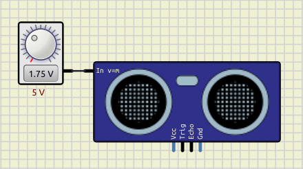
Ultrasonic distance sensor.

Feed a voltage at “Dist.” Pin (left side) to simulate distance.
Volts equal to meters.

For example 1.75 Volts will set a distance of 1.75 meters:

sr04_dist.png


Temperature and humidity sensor.


Properties:

Property: (default value)

  • Model: (HDT22)
    Choose model: HDT22 or HDT11.

  • Temp. increment: (0.5 ºC)
    Temperature will increment by this value when + or - buttons are pushed.

  • Humid. increment: (0.5 ºC)
    Humidity will increment by this value when + or - buttons are pushed.


Use:

To change values click in “+” and “-” buttons.
This will change the value of the active unit: the one with the black square.

To change the active unit click just left of the number, then the black square will change to that unit:

dht22_ui.png


Resources:


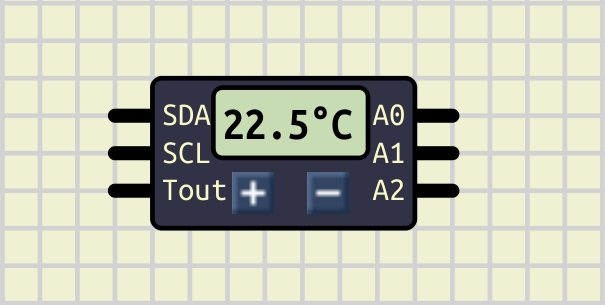
Temperature sensor with I2C interface.


Properties:

Property: (default value)

  • Temperature: (22.5 ºC)
    Current temperature.

  • Temp. increment: (0.5 ºC)
    Temperature will increment by this value when + or - buttons are pushed.


Use:

Pins A0, A1, A2 are used to set the 3 lower bits of the address.

To change temperature use “+” and “-” buttons:

ds1621_use.png


Temperature sensor with One Wire interface.


Properties:

Property: (default value)

  • ROM: (random)
    ROM address.

  • Temperature: (22 ºC)
    Current temperature.

  • Temp. increment: (0.5 ºC)
    Temperature will increment by this value when + or - buttons are pushed.


Use:

To change temperature use “+” and “-” buttons.


Peripherals

Connection to a real or virtual Serial Port in your PC.

Configure Port Name and click “Open” button to connect to that serial port.
“Port Name” must be an existing port in your PC with read/write permissions.


Properties:

Property: (default value)

Main:

  • Auto Open: (no)
    Open port automatically at Simulation start.

  • Port Name: ()
    Name of the Serial Port to connect to.

Config:

  • Baudrate: (9600)
    Transmission speed.

  • Data Bits: (8)
    Number of data bits.

  • Stop Bits: (1)
    Number of stop bits.


Resources:

Videos:


Serial terminal is a component to send and receive data to any UART devices in the simulation.


Properties:

Property: (default value)

  • Baudrate: (9600)
    Transmission speed.

  • Data Bits: (8)
    Number of data bits.

  • Stop Bits: (1)
    Number of stop bits.


Use:

Connect Tx pin to other device Rx pin.
And Rx pin to other device Tx pin:

serterm_use.png

Click “Open” button to open the Serial Monitor and see messages received or send your data.

The serial monitor is divided in two panels:

  • Right panel: shows the data sent.
  • Left panel: shows the data received.

ser_term.png

There are “Clear” buttons for each panel at the bottom.
To pause/ Resume logging data use the Pause button at the top left.

Use “Send Text” input box to send ascii characters.
Activating the “CR” button will add a return character to the text.

Use “Send Value” input box to send 0-255 values.

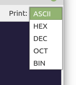
You can choose to print the data sent/received in different formats.
Click in the button at the top right side and choose from the list:

ser_print.png
  • ASCII: Default.
  • HEX: Hexadecimal (0x00)
  • DEC: Decimal.
  • OCT: Octal.
  • BIN: Binary (8 bits).

Resistive touchpad.


Properties:

Property: (default value)

Main:

  • Width: (240 pixels)

  • Height: (320 pixels)

  • Transparent: (no)

Electric:

  • RxMin: (100 Ω)
    Minimum resistance in X axis (right side).

  • RxMax: (100 Ω)
    Maximum resistance in X axis (left side).

  • RyMin: (100 Ω)
    Minimum resistance in Y axis (top side).

  • RyMax: (100 Ω)
    Maximum resistance in Y axis (bottom side).


Resistive joystick.

Click and move the circle in the midlle.


Relative rotary encoder.


Properties:

Property: (default value)

  • Steps per Rotation: (20)
    Encoder steps per dial rotation.

Real time clock with I2C interface.


Properties:

Property: (default value)

  • Set current time at start: (yes)
    Start simulation at current time (time from your PC).

Wifi module.

Partial implementation of TCP/IP AT Commands.


Properties:

Property: (default value)

  • Baudrate: (115200)
    Transmission speed.

  • Show Debug messages: (yes)
    Show debug messages in bottom panel.


Logic / Gates

Configurable Buffer Gate.


Properties:

Property: (default value)

Electric:

Logic Components#Inputs
- Invert Inputs: (no)
Invert input pins.

Logic Components#Outputs
Gate outputs
- Tristate: (no)
If yes, creates an enable pin (active Low).
When disabled, output is high impedance.

Gate timing


Configurable And Gate.


Properties:

Property: (default value)

Electric:

Logic Components#Inputs
Gate Inputs
Logic Components#Outputs
Gate outputs
Gate timing


Configurable Or Gate.


Properties:

Property: (default value)

Electric:

Logic Components#Inputs
Gate Inputs
Logic Components#Outputs
Gate outputs
Gate timing


Configurable XOr Gate.


Properties:

Property: (default value)

Electric:

Logic Components#Inputs
- Invert Inputs: (no)
Invert input pins.

Logic Components#Outputs
Gate outputs
Gate timing


Logic / Arithmetic

Binary counter.
Sets the output High after a number of clock pulses.


Properties:

Property: (default value)

Main:

  • Use Set Pin: (no)
    Shows/hides “Set” pin.

  • Clock Inverted: (no)
    Invert Clock pin.

  • Set/Reset Inverted: (yes)
    Invert Set and Reset pins.

  • Count to: (1)
    Number of Clock pulses to set output High.

Electric:

Logic Components#Inputs
Logic Components#Outputs
Logic Components#Timing

Configurable full adder.


Properties:

Property: (default value)

Electric:

Logic Components#Inputs
Logic Components#Outputs
Logic Components#Timing

8 bit shift register.


Properties:

Property: (default value)

Main:

  • Clock Inverted: (no)
    Invert Clock pin.

  • Reset Inverted: (yes)
    Invert Reset pin.

Electric:

Logic Components#Inputs
Logic Components#Outputs - Invert Outputs: (no) Invert output pin.

  • Open Drain: (no)
    If yes, output act as an open drain:
    It can sink but not source current.

Logic Components#Timing

Combinational Logic device.
Set a function for each output clicking in it’s button.

Function Full tutorial


Properties:

Property: (default value)

Main:

  • Functions: (i0 | i1) List of functions (separated by comma).

Electric:

Logic Components#Inputs
- Input size: (2 Pins) Number of input pins.

  • Invert Inputs: (no) Invert input pins.

Logic Components#Outputs
- Output size: (1 Pins) Number of output pins.

  • Invert Outputs: (no) Invert output pins.

  • Open Drain: (no) If yes, output act as an open drain: It can sink but not source current.

Logic Components#Timing

Logic / Memory

Flipflop “D” type.


Properties:

Property: (default value)

Main:

  • Use Set/Reset Pin: (no)
    Shows/hides Set and Reset pins.

  • Set/Reset Inverted: (yes)
    Invert Set and Reset pins.

  • Clock Inverted: (no)
    Invert Clock pin.

  • Trigger Type: (Clock)
    “Clock” triggers every active edge.
    “enable” any change during active state.
    “None” hides Clock pin.

Electric:

Logic Components#Inputs
Logic Components#Outputs
Logic Components#Timing

Flipflop “T” type.


Properties:

Property: (default value)

Main:

  • Use Set/Reset Pin: (no)
    Shows/hides Set and Reset pins.

  • Set/Reset Inverted: (yes)
    Invert Set and Reset pins.

  • Clock Inverted: (no)
    Invert Clock pin.

  • Trigger Type: (Clock)
    “Clock” triggers every active edge.
    “enable” any change during active state.
    “None” hides Clock pin.

Electric:

Logic Components#Inputs
Logic Components#Outputs
Logic Components#Timing

Flipflop “RS” type.


Properties:

Property: (default value)

Main:

  • Set/Reset Inverted: (yes)
    Invert Set and Reset pins.

  • Clock Inverted: (no)
    Invert Clock pin.

  • Trigger Type: (Clock)
    “Clock” triggers every active edge.
    “enable” any change during active state.
    “None” hides Clock pin.

Electric:

Logic Components#Inputs
Logic Components#Outputs
Logic Components#Timing

Flipflop “JK” type.


Properties:

Property: (default value)

Main:

  • Use Set/Reset Pin: (no)
    Shows/hides Set and Reset pins.

  • Set/Reset Inverted: (yes)
    Invert Set and Reset pins.

  • Clock Inverted: (no)
    Invert Clock pin.

  • Trigger Type: (Clock)
    “Clock” triggers every active edge.
    “enable” any change during active state.
    “None” hides Clock pin.

Electric:

Logic Components#Inputs
Logic Components#Outputs
Logic Components#Timing

Configurable latch.


Properties:

Property: (default value)

Main:

  • Input Size: (8 Channels)
    Number of channels.

  • Trigger Type: (Enable)
    “Clock” triggers every active edge.
    “enable” any change during active state.
    “None” hides Clock pin.

  • Invert Outputs: (no)
    Invert output pins.

Electric:

Logic Components#Inputs
Logic Components#Outputs
- Tristate: (yes)
If yes, creates an enable pin (active Low).
When disabled, output is high impedance.

  • Open Drain: (no)
    If yes, output act as an open drain:
    It can sink but not source current.

Logic Components#Timing

Static RAM/ROM.

This component can be configured as Ram or Rom by setting persistance property.
You must save the circuit to get data persistance.

To watch Memory content:
Right-Click and select “Show Memory Table”.

You can also save memory data to a file and load from file:
Right-Click and select “Load data” or “Save data”.


Properties:

Property: (default value)

Main:

  • Address Size: (8 Bits)
    Number of bits of address bus.
    This determines the capacity (words = 2^Address_Size)

  • Data size: (8)
    Number of bits of data bus.
    This determines the length of a memory word.

  • Persistent: (no)
    Save data to circuit file.
    If yes it acts as a ROM.

  • Asynchronous: (no)
    If yes it will be active while selected.
    If no only active in CS pin active edge.

Electric:

Logic Components#Inputs
Logic Components#Outputs
- Tristate: (yes)
If yes, creates an enable pin (active Low).
When disabled, output is high impedance.

  • Open Drain: (yes)
    If yes, output act as an open drain:
    It can sink but not source current.

Logic Components#Timing

Dynamic RAM.

To watch Memory content:
Right-Click and select “Show Memory Table”.

You can also save memory data to a file and load from file:
Right-Click and select “Load data” or “Save data”.


Properties:

Property: (default value)

Main:

  • Row Address Size: (8 Bits)
    Number of bits of Rows of the Memory array.
    This determines the total capacity (words = 2^Rows * 2^Columns)

  • Column Address Size: (8 Bits)
    Number of bits of Columns of the Memory array..
    This determines the total capacity (words = 2^Rows * 2^Columns)

  • Data size: (8)
    Number of bits of data bus.
    This determines the length of a memory word.

  • Refresh period: (0 ps)
    Maximum time between Memory refreshes.

Electric:

Logic Components#Inputs
Logic Components#Outputs
- Tristate: (yes)
If yes, creates an enable pin (active Low).
When disabled, output is high impedance.

  • Open Drain: (yes)
    If yes, output act as an open drain:
    It can sink but not source current.

Logic Components#Timing

I2C RAM/ROM.

This component can be configured as Ram or Rom by setting persistance property.
You must save the circuit to get data persistance.

To watch Memory content:
Right-Click and select “Show Memory Table”.

You can also save memory data to a file and load from file:
Right-Click and select “Load data” or “Save data”.


Properties:

Property: (default value)

  • Size: (65536 bytes)
    Size in bytes.

  • Control Code: (80)
    Device address.

  • I2C Frequency: (100 KHz)
    It is better to be similar to I2C Master frequency, but not critical in most cases.

  • Persistent: (no)
    Save data to circuit file.
    If yes it acts as a ROM.


Logic / Converters

Digital Multiplexer.


Properties:

Property: (default value)

Main:

  • Address Size: (3 Bits)
    Number of select pins.
    Determines number of channels: n = 2^Address_Size

Electric:

Logic Components#Inputs
- Invert Inputs: (no)
Invert input pins.

Logic Components#Outputs
Logic Components#Timing

Digital Demultiplexer.


Properties:

Property: (default value)

Main:

  • Address Size: (3 Bits)
    Number of select pins.
    Determines number of channels: n = 2^Address_Size

Electric:

Logic Components#Inputs
Logic Components#Outputs
- Invert Outputs: (no)
Invert output pins.

Logic Components#Timing

Converts from binary to decimal.


Properties:

Property: (default value)

Main:

  • 16 Bits: (no)
    8 or 16 outputs.

Electric:

Logic Components#Inputs
Logic Components#Outputs
- Invert Outputs: (no)
Invert output pins.

Logic Components#Timing

Converts from decimal to binary.


Properties:

Property: (default value)

Main:

  • 16 Bits: (no)
    8 or 16 inputs.

Electric:

Logic Components#Inputs
- Invert Inputs: (no)
Invert input pins.

Logic Components#Outputs
Logic Components#Timing

Converts from decimal to seven segment.


Properties:

Property: (default value)

Electric:

Logic Components#Inputs
- Invert Inputs: (no) Invert input pins.

Logic Components#Outputs
- Invert Outputs: (no)
Invert output pins.

  • Open Drain: (yes)
    If yes, output act as an open drain:
    It can sink but not source current.

Logic Components#Timing

I2C to Parallel interface.


Properties:

Property: (default value)

  • Control Code: (80)
    Device base address.

  • I2C Frequency: (100 KHz)
    It is better to be similar to I2C Master frequency, but not critical in most cases.


Logic / Other

Analog to Digital Converter.


Properties:

Property: (default value)

Main:

  • Size: (8 Bits)
    Number of output pins.

  • Reference Voltage: (5 V)
    Voltage asigned to the maximum value.

Electric:

Logic Components#Outputs
- Invert Outputs: (no)
Invert output pins.

  • Open Drain: (yes)
    If yes, output act as an open drain:
    It can sink but not source current.

Logic Components#Timing

Digital to Analog Converter.


Properties:

Property: (default value)

Main:

  • Size: (8 Bits)
    Number of input pins.

  • Reference Voltage: (5 V)
    Voltage asigned to the maximum value.

Electric:

Logic Components#Inputs
- Invert Inputs: (no) Invert input pins.

Logic Components#Timing

7 segment display with integrated BCD to 7segment converter.

Bit 0 in right pin, bit 3 in left pin.

Does not work with PWM or multiplexing.


Properties:

Property: (default value)

  • Show Point Pin: (no) If yes, show a Pin to manage decimal point indicator.

  • Show Enable Pin: (no) If yes, show a Pin to Enable/Disable the device.

Description:

LM555 timer.


Connectors

Configurable Bus connector.


Properties:

Property: (default value)

  • Size: (8 Bits)
    Number of pins.

  • Start bit: (0)
    Bit number asigned to first pin..


Hidden connection.


Properties:

Property: (default value)

  • Id: ()
    Identifier, all Tunnels with this Id will be connected togeter.

  • Bus: (false)
    Whether this tunnel connects to a Bus or not.


Configurable socket connector.


Properties:

Property: (default value)

  • Size: (8 Pins)
    Number of pins.

Resources:


Graphical

Embedded Image.


Shape

Configurable Text Box.


Properties:

Property: (default value)

Main:

  • Margin: (5 Pixels)
    Space between text and border.

  • Border: (1 Pixels)
    Width of border line.

  • Background Color: (ffffdc)
    Click on the color box to choose a new background color.

  • Opacity: (1)
    Value from 0 to 1:
    0 for transparent to 1 for 100% opaque.

Text:

  • Font: (Helvetica)
    Font family

  • Font Size: (10 Pixels)
    Font size in pixels.

  • Font Color: (000080)
    Click on the color box to choose a new font color.

  • Fixed Width: (yes)
    Characters have constant width or not.

  • Text Box:
    Edit the text here.


Configurable Rectangle.


Shape

Configurable Ellipse.


Shape

Configurable Line.


Shape

Other

A Package Component is only an interface to create package files.
It is located in the Component list in category Other.

Creating Package File.

When you add this component to the circuit it is just a blue box, that’s an empty package ready to be configured:

pkg1.png

From here you can load an existing package file to edit it or create a new package.
To load or save a package file, Right-Click on it to open context menu.

Don’t forget to save the package file when you finish!!


Configuring Package:

To configure the package open Properties in the context menu:

pkg_props.png

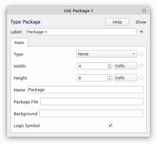
  • Type: There are 3 types available:
    1. None: normal subcircuit (if not sure use this).
    2. Logic: subcircuit with properties to configure all logic components inside.
    3. Board: subcircuit with graphic components .
    4. Module: this is a Board that can be stacked on top of other boards.
  • Width: width of the package in grid cells.
  • Height: height of the package in grid cells.
  • Name: There are 3 options:
    1. Empty: no name in the package.
    2. “Package”: uses the package file name.
    3. “Any name you want”: custom name.
  • Package File: path to the package file.
  • Background: path to image or “color(r,g,b)”.
  • Logic Symbol:  Chip or Logic Symbol.

Creating new Pins:

If you hover the mouse pointer along the package edges while pressing Shift Key you will see a grey fake pin.
If you keep Shift key and move the mouse pointer, the fake pin will move, so you can place the pin at any position in the package.

When the fake pin is correctly placed, mouse-click and a real Pin will appear.
At the same time a dialog will appear to configure the Pin:

edit_pin.png

  • Pin Name: Label shown in the package.
  • Pin Id: Unique Pin Id.
  • Space to Pin: Space between Label and Pin in pixels.
  • Pin Angle: Angle of the Pin depending of position: Right, Left, Top, Bottom.
  • Invert Pin: Pin Shows as inverted.
  • Unused Pin: Inactive Pin
  • Point Pin: Makes Pin Length = 0.

Editing Pins:

You can edit existing pins by right-clicking on the edge of the package at the pin position.
A context menu will appear with pin options:

  • Move: Click and move Pin.
  • Edit: Opens Edit Pin Dialog.
  • Delete: Remove Pin.

Package variants:

There are 2 possible package variants: Chip and Logic Symbol.
It is possible to have both options for the same component and switch between them:

packages.png

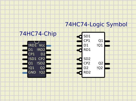
There are some considerations to have in mind when you create both Chip and Logic Symbol packages for the same component. Both Packages must be Pin-compatible in order to work with the same subcircuit file:

  • All active Pins must exist in both packages ( doesn’t apply to unused pins).
  • Same Pin must have same Id in both packages.

Note that There is an “Id” and a “Label” for each pin, so a pin can have different labels in both packages while the Id must be the same.
As an example in the image above, for 74HC74 some pins have slightly different labels: !RD1 vs RD1 for example.

For inverted pins you can either use “!” as the first character of the label or set the pin as inverted.
It is recommended to use “!PinName” for Chip packages and “PinName”+invert-Pin for Logic Symbol packages, but in some cases you can use “!PinName” for both, for example “!Qn” outputs in 74HC74 package above.

This is a standalone dial ment to be linked to other Dialed components like Potentiometer, Variable Resistor or Resistive Sensors.

This is useful in several cases like dual potentiometers or using sliders in combination with screens, but also to create different components with scripts.


Properties:

Property: (default value)

Main:

  • Minimum Value: (0)
    Value with dial at the left end.

  • Maximum Value: (1000 )
    Value with dial at the right end.

  • Steps: (0 )
    Number of steps of the movement.

Dial:

  • Slider: (false)
    true: Slider control.
    false: Knob control.

  • Scale: (1)
    Determines the size of the dial.


Resources: