(Simulide R2116 or higher.) DF340A.
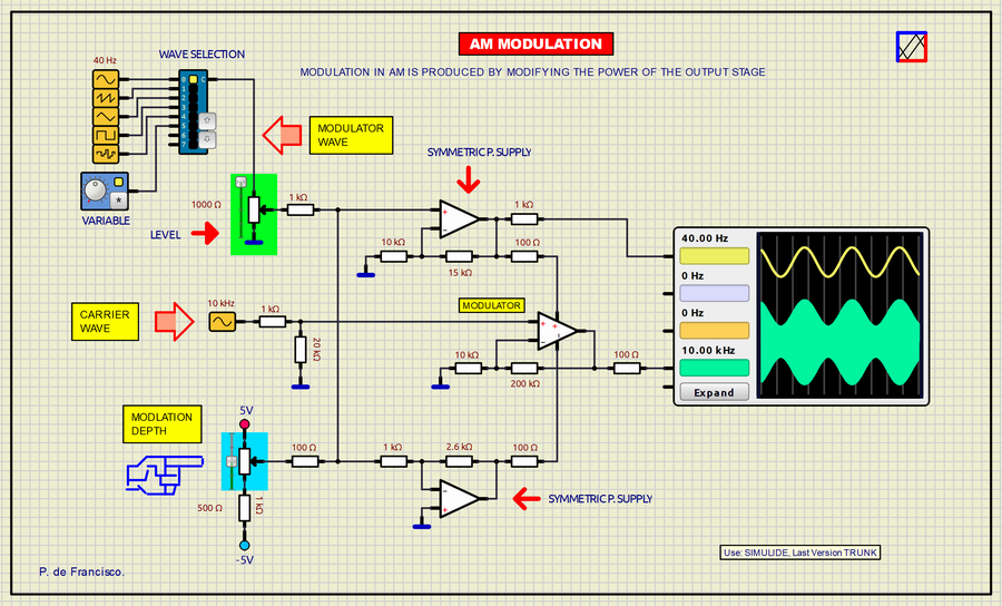
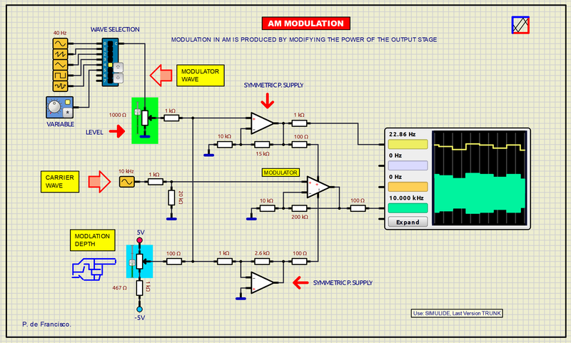
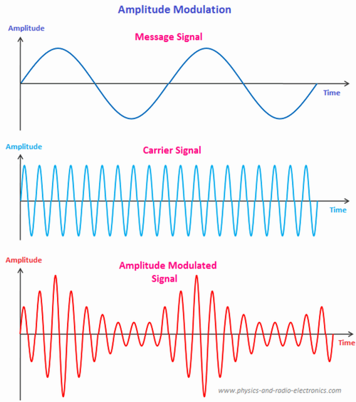
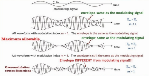
Modulation in AM is obtained by modifying the power of the modulating stage so that the positive and negative half-waves of the carrier wave are modulated with a phase shift of 180 degrees with the same modulating signal, otherwise what is called overmodulation occurs. which leaves the carrier at a constant amplitude and therefore the emission of the signal does not occur.
The AM broadcast of commercial radio stations, amateur radio stations and others has been replaced by FM broadcasting, which has advantages in terms of broadcast quality due to its lower sensitivity to disturbances. However, AM is still used due to the simplicity of the system in general, both in emission and reception. The commercial AM band is between 500 kHz and 1700 kHz.
In this porject we use a much lower carrier frequency, 10kHz because what we intend is simply to do a practical simulation of this type of modulation. The modulator signal must be noticeably lower than that of the carrier, in our case 40 Hz as a base. At the output of the diagram on the oscilloscope, the modulating signal and the already modulated carrier are shown. To manage this modulator we have three controls:
- a) Modulator wave type switch.
- b) A potentiometer to control the level of the modulating signal.
- c) A potentiometer to control modulation depth
To know more about AM modulation: https://en.wikipedia.org/wiki/Amplitude_modulation
SCHEME:
The circuit in our example is composed of three operational amplifiers that do all the operation with a symmetrical 5V supply (+5V and -5V). The output opamp directly receives the 10kHz carrier wave and the 40 Hz modulating signal is introduced into its positive and negative power inputs. At the positive power input its opamp is amplification with a phase shift of ZERO degrees and in the power supply negative with a phase shift of 180 degrees. The input of these opamps is common and is controlled by two potentiometers: One to adjust the signal input LEVEL and another to adjust the carrier modulation DEPTH, 50% is a standard setting. At the input of the level potentiometer, a switch has been provided to select the type of wave to be emitted: Sinusoidal, sawtooth, triangular, square, random and an input of a variable oscillator. The output of the modulator stage and that of the zero phase shift opamp have been applied to the oscilloscope.
AM-MODULATOR AND SIMPLE DEMODUL. (Simulide, R2094 or higher). DF340B
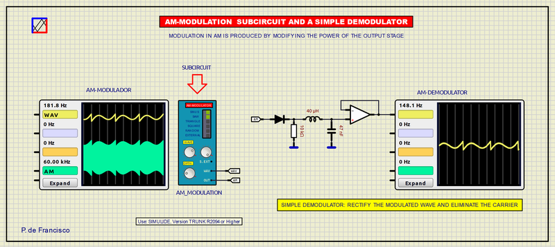
This Project is an AM modulator and a simple demodulator. The modulator is a subcircuit with the diagram of example 340. The carrier wave is a 30 kHz sine wave (Changeable by clicking on the modulator). The modulating wave is 40 Hz.The demodulator is composed of a rectifier diode to eliminate the negative half-wave and an LC filter to eliminate carrier remains.
The modulator oscilloscope shows the modulated and modulating wave. On demodulator oscilloscope shows the modulating wave extracted from the AM.
MODULATOR CONTROLS:
a) Waveform selector with EXT position to connect another oscillator (Pressing several positions simultaneously shows curious modulations).
b) The potentiometer next to EXT adjusts its input level.
c) WAVE: Adjust the level of the modulating signal.
d) DPTH: Adjust the modulation depth.
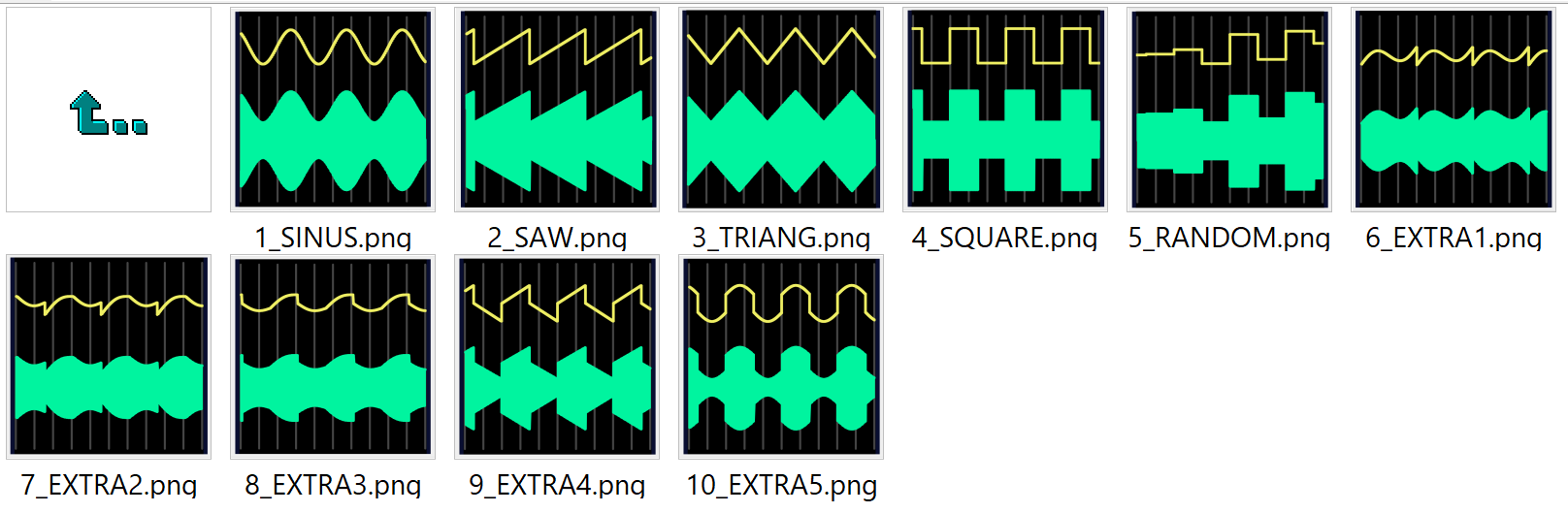
Examples of modulations achieved with the modulator subcircuit:
The modulator subcircuit contains the same structure of the modulator already discussed.

OVERMODULATION. (Simulide, TRUNK R2094 or higher). DF340C.
This scheme corresponds to a circuit that adds the carrier plus the modulating signal. Here in the positive and negative half waves the modulating wave is in phase, this is called OVERMODULATION where it can be seen that the carrier always maintains the same amplitude. In this case, there is no amplitude modulation, so the signal could not be broadcast.
MISCELLANY:
The attached zip file typically includes:
1) Electrical diagram.
2) “data” folder.
SUBCIRCUITS:
This example integrates several subcircuits located in the “data” folder into the ZIP attached. This folder must always be next to the “sim1” scheme so that it can be executed. A subcircuit is a “custom” circuit that accumulates a set of Simulide base components (primitive function) to obtain a new or an adapted function. These subcircuits are treated by Simulide as another component of its own structure. User can create his own subcircuits or use the ones published here in your own designs once the procedure is known, explained in detail in the Simulide tutorials: https://simulide.com/p/subcircuits/
* Communication with the author: Simulide/User/Messages/Defran
Downloads: