MEASURE PULSES PER MINUTE__(DF331)
PURPOSE.
The objective of this project is to count pulses in one minute. The measurement of each minute needs to be activated manually. If the signal is regular, the number of pulses will be the same between minutes.
There are two counting modes:
a) Counting in one minute. This measurement gives complete precision but requires a time of one minute to obtain the result.
b) Counting in 6 seconds. In this mode the measurement is obtained much earlier but with less precision. This mode is useful for making estimates.
The keystroke count is shown at all times on an eight-digit, 7-segment LED display without non-significant zeros on the left for greater reading comfort.
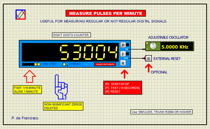
USE.
The counter has two measurement modes depending on the position of the <F> (FAST) switch:
a) <F> OFF LINE. (The counter will need one minute to obtain the measurement. The yellow LED on the right will be OFF in this position.
b) <F> CONNECTED. The counter will run for six seconds. The result is obtained more quickly but with less precision. The number that appears on the screen will always have the digit of the units at zero, this is due to the decrease in precision. Example: if the display shows 14560, the real pulses could be between 14560 and 14569 pulses per minute. The LED will be ON in this position.
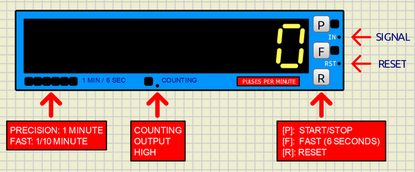
At the bottom left is the “TIME ADVANCE”. Here six LEDs show the elapsed measurement time in a “curtain” format. It will move to the left at a speed of 10 seconds per LED at the one minute measuring position and 1 second per LED at the 6 second measuring position. When the measurement time has elapsed, the display will stop counting showing the final value of pulses, at this time the “TIME ADVANCE” LEDs will take the pattern: 101101 as the end of counting signal.
Pressing the <R> button clears the counter and the process begins again. The counting does not start automatically.
DIAGRAM.
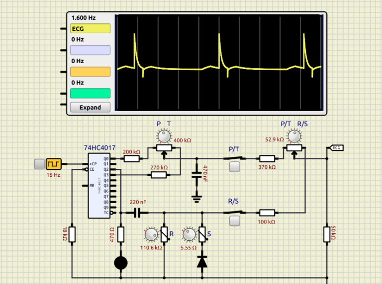
The following figure shows the circuit diagram that makes up the pulses per minute counter. Its functional parts are described below:
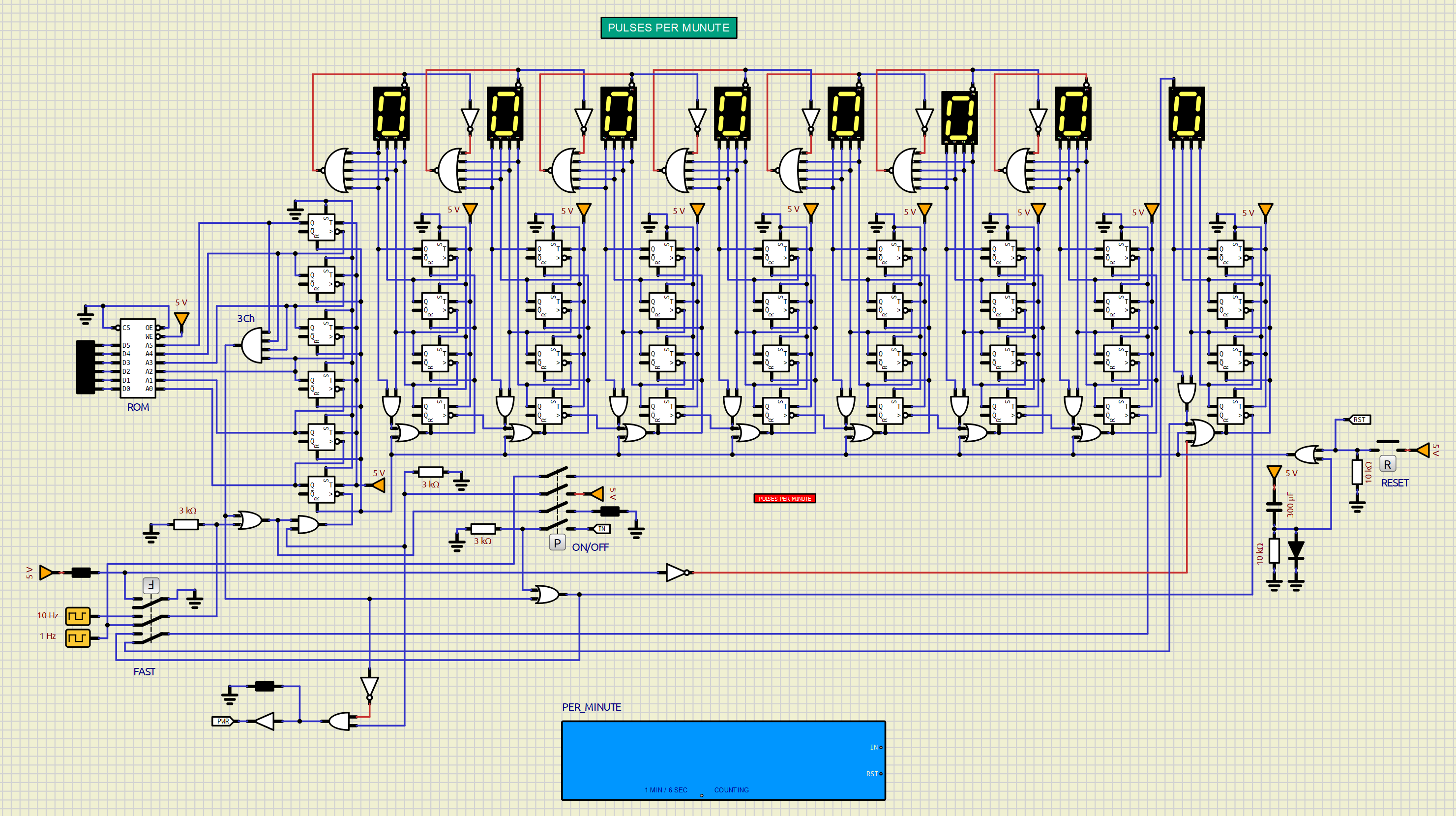
The pulse counter:
The pulse count is shown on an eight-digit 7-segment type display, which can reach up to 99999999. Each of these digits are separate units that work here in BCD (Binary Coded Decimal), therefore one digit It will have a 4-bit input numbered 1, 2, 4 and 8 corresponding to its binary weight.
These four inputs are connected to the outputs of 4 T-type flip-flops (toggle) that make up a 4-bit counter. For this counter to operate in BCD there is a two-input AND gate, connected to weighted outputs 2 and 8, which resets the counter when the hexadecimal value “A” (1010) is reached. This prevents all other Hexadecimal states above nine.
The input to the binary time counter receives the clock signal selected by the <F> switch which can be 1 Hz for Slow Measurement Mode or 10 Hz for Fast Measurement Mode.
Erasing non-significant zeros on the left:
At the output of the counters there is a 5-input NOR gate whose output turns off its own display whenever its four inputs are at zero and in the previous digit there is a number other than zero, for this the fifth input takes the previous digit signal. This device prevents a number zero preceded by another number other than zero from turning off the display of its own digit.
Example: In 00078340 the three left zeros are turned OFF, but not the right zero.
In order for each display to be turned off, “Show Enable Pin” must be checked in Porperties.
The time counter:
A counter with 6 flip-flops counts up to 60, 3C in hexadecimal and 0011 1100 in binary. Therefore, an AND gate with four inputs connected to the four bits at 1 of the counter acts as a decoder to stop the counting and display the number of pulses reached.
TIME ADVANCE:
Since one minute of pulse counting is a relatively long waiting time, a 6-LED display has been provided to show the progress of time in the form of a curtain.
A ROM memory provides the pattern that will be displayed on the 6 LED strip to see the progress of time. The following figure shows the content of this ROM, which is obtained by clicking on it in “Show Memory Table”. In this table a progression of ones in binary will produce the LEDs turning on. In the Last positions is the Value 2Dh, that is 0010 1101 whose right 6 bits are the end of counting time signal pattern.
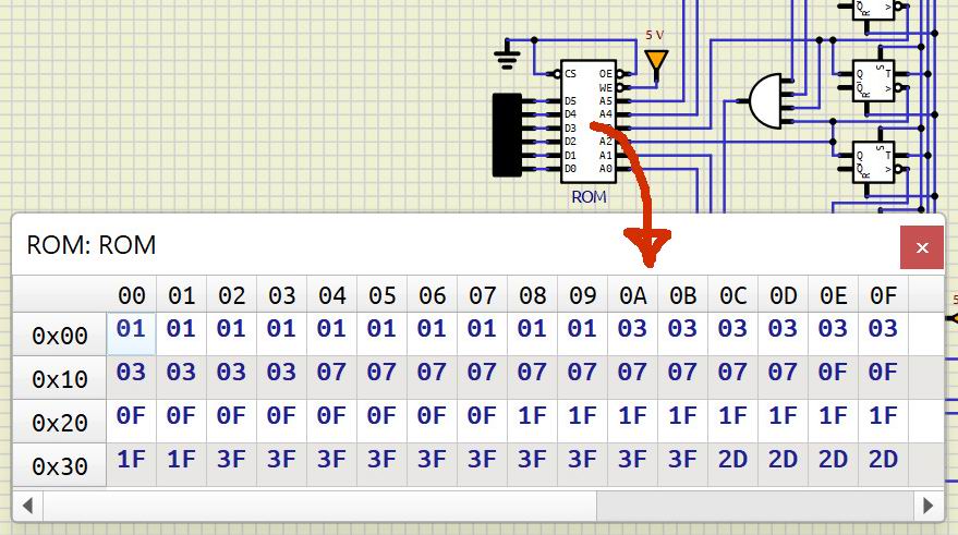
The content of the ROM can be created in hexadecimal directly in the ROM in the “Show Memory Table” by writing the content in each position (0x3f for example) or loaded from a text file. The content of the ROM can also be saved in a text file.
All this hardware is concentrated in a subcircuit whose concept is discussed in the following section. This subcircuit will appear in Simulide as one more component that can be used in other schemes in which a pulse meter of this type is required.
MISCELLANY.
The attached zip file typically includes:
1) Electrical diagram.
2) “data” folder.
This data folder contains the subcircuits (custom) created by the author. The presence of this folder is necessary for the execution of the project.