
STEPPER MOTOR STUDIO AND TRAINING__(DF322)
CONCEPTS: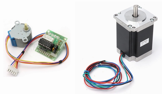 A Stepper Motor is a brushless direct current motor intended for use in controlled mechanical movement and precision systems. This motor moves in steps from 0 to 360 degrees. It is composed of a stator with paired windings arranged to give a 4-term connectivity (with or without common point) and grooves in the air gap to obtain the rotation in degrees.
The rotor is a powerful magnet, also ribbed. The movement is obtained by applying a sequence of pulses to the four terminals of the stator winding, this sequence is called a pulse pattern that must be applied continuously.
 Varieties:
Regarding the structure of the rotor winding, there are two types to obtain different powers and control structures:
- Bipolar, where the two ends of each of the two windings, called A+, A-, B+, B-. , They are free.
- Bipolar with COMMON POINT: the two coils have a common point that is connected to ground A+, A-, B+, B- and GND.
Regarding its use, there are three standard types:
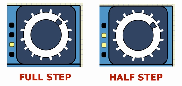
- Full step: The rotor moves with less precision facing the grooves.
- half step: Greater precision is obtained: The rotor is trimmed in the grooves and in the middle of them.
- Microstepping: with this system you obtain a continuous movement in steps. Its principle is to apply micropulses of advance between grooves. For this movement, extra hardware is required and therefore a specific control.
 PURPOSE:
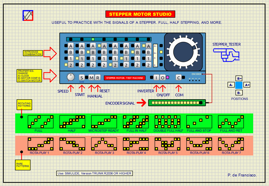
This project is based on a desk with all the controls to make simulations of rotation patterns on the motor terminals A+, B+, B- and B– here called respectively A, B, 1, 2. The desk is divided into two parts:
- Upper, there is the motor with access to its terminals whose sequence of patterns can be programmed simply by pressing the switches. In this way you can obtain all types of movements: FULLSEPPING, HALFSTEPPING and others. Practicing with invented patterns can be a curious and instructive experience. The complete sequence is 16 positions. At the top, 16 LEDs show the rotation point at all times. A series of patterns are included in the scheme. In the green band there are some typical rotation patterns and in the red band there are experimental patterns.
- Below are the controls that we detail whose function we detail:
- <SPEED>: POTENTIOMETER: Turning speed.
- <S> START: Start rotation.
- <M> MAN: Manual advance of the rotor with each press.
- <R> RESET: Go to the beginning of the pattern.
- <I> INVERTER: Inversion of rotation.
- <O> MOTOR ON/OFF: Start and stop of the rotor.
- <C> COMMON: Connection and disconnection of the common point of the windings.
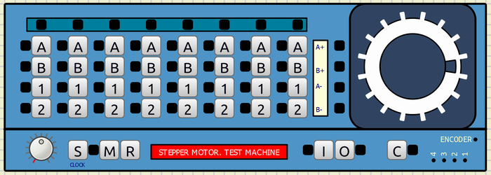
At the bottom right are the four available motor outputs and also the encoder output. The encoder in a motor is useful, among other things, to know where the rotor is physically located to verify that the movement has been executed and there is no jam.
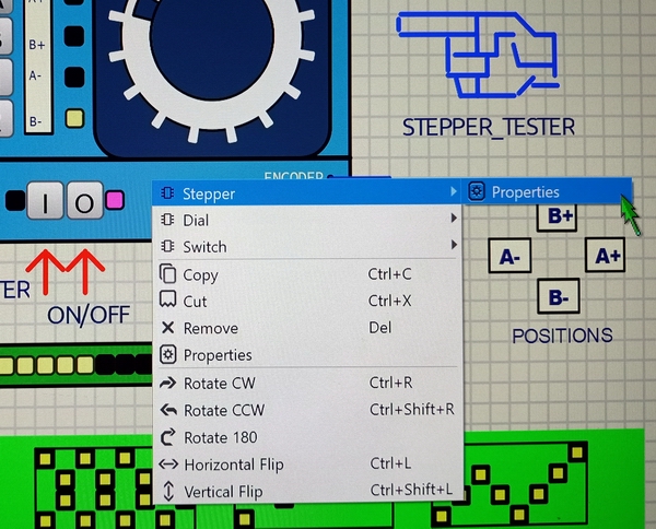
Accessible internal configurations:
Using the right mouse button you can access three internal configurations of the subcircuit:
- Stepper: motor configuration.
- Dial: Change of frequency range of the oscillator.
- Switch: functional change of the ON/OFF switch
USE:
The use of this project is practically commented. By loading the scheme in Simulide and running it, you can type the pattern to test. To see its effect on the motor, you can produce the step-by-step movement manually by pressing <M> or automatically by pressing <S>. The movement will immediately begin. The step progress is seen above in the green bar. With the <SPEED> potentiometer you can adjust the forward speed. <R> resets the movement going to the first position. <I> reverses the rotation of the rotor at all times. <O> is the motor power supply switch. <C> connects the common point of the winding.
ENCODER SIGNAL shows the encoder signal and therefore the movement of the rotor.
DIAGRAM:
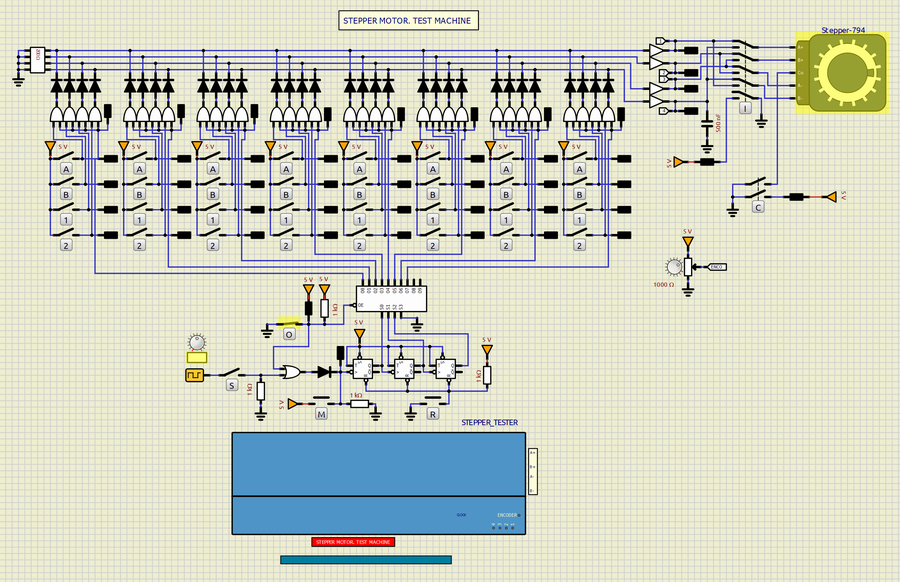
It is based on asubcircuit made with pure hardware and using Simulide’s internal components:
You can see its structure in the “data” folder STEPPER_TESTER, file STEPPER_TESTER.sim1.
A counter followed by a decoder sequentially opens each of the 8 combinations. These combinations are added using a large diode-based wired OR. After these diodes, four amplifiers provide the signal to the motor but before the motor, a crossover switch produces the inversion.
The clock signal that moves the counter is produced by a Simulide generator linked to a potentiometer. In the manual position <M>, the pulses are provided by the button itself.
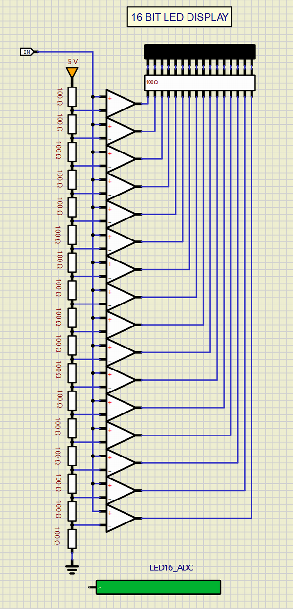
A 16 opamp-based LED strip connected to the output of the motor encoder linearly and graphically displays the position of the rotor at each turn. This is achieved by the LED16_ADC subcircuit.
MISCELLANY:
The attached zip file typically includes:
1) Electrical diagram.
2) “data” folder.
This data folder contains the subcircuits (custom) created by the author. The presence of this folder is necessary for the execution of the project.
SUBCIRCUIT:
It is a “custom” circuit that accumulates a set of Simulide base components to obtain a new or an adapted function. These subcircuits are treated by Simulide as another component of its own structure.
Subcircuits are very useful to create a component that does not exist in the simulide set, to compress a complete schematic in a single block and thus improve the complexity and compression of the final circuit where it is integrated or for any other function that you want to have available when making a schematic.
The subcircuits must be properly incorporated in the “data” folder of simulide, in the “User Data” folder or in the “data” scheme folder that must be attached together with the schematic of the project itself. Attaching the subcircuits to the Simulide “data” folder is not advisable because they can be lost with updates to it. Attaching them in “User Data” is the correct thing to do. Attaching it to the “data” folder of the diagram is necessary when it is shared.
Creating and locating a subcircuit is simple once you know the procedure that is explained in detail in the simulide tutorials: https://simulide.com/p/subcircuits/
RESOURCES:
STEPPER MOTOR.
STEPPER MOTOR, Microstepping.
Wikipedi. Stepper Motor.
Great project.
Very useful to understand how Steppers work and to experiment with different patterns.