ECG signal generator.
Introduction:
This article presents a detailed explanation of an ECG signal generator circuit built using a 74HC4017 decade counter. The circuit enables users to modify the wave shape of the ECG signal, allowing for a more comprehensive understanding of the cardiac activity.
 ECG signal:
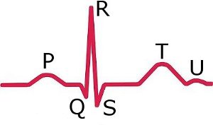
There are three main components to an ECG:
- The P wave, which represents depolarization of the atria.
- The QRS complex, which represents depolarization of the ventricles.
- The T wave, which represents repolarization of the ventricles.
In this circuit you can modify the wave shape using several potentiometers to control different parts of the wave and 2 switches to activate/deactivate the 2 main branches.
Circuit Description:
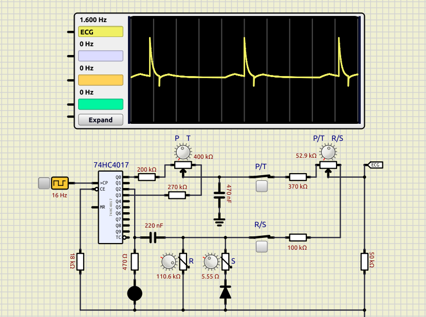
The ECG signal generator circuit is constructed using a 74HC4017 decade counter, which is a high-speed, low-power CMOS counter.
The pulse train is created by connecting the output of the 74HC4017 to a series of resistors and capacitors, which shape the waveform of the ECG signal.
These resistors and capacitors are adjusted to control the amplitude, duration, and shape of the ECG signal. The outputs of the 74HC4017 are arranged in 2 branches:
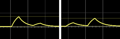
- P/T Branch: Output Q0 generates the P pulse and output Q3 generates The T pulse. These 2 pulsed are combined to form the P/T branch.
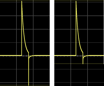
- R/S Branch: Output Q2 generates a pulse that is divided in 2 pulses: R and S.
These 2 branches are then mixed to generate the complete signal.
There are 2 switches to connect/disconnect each of the main branches from the output and see which parts of the signal are actually controlled by each branch.
There are 2 potentiometers and 2 variable resistors to control each component of the signal:
– P T: Potentiometer controlling the proportion of P respect to T components in P/T branch.
– P/T R/S: Potentiometer controlling the proportion between the 2 branches: P/T and R/S.
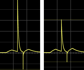
– R: Variable resistors controlling the R peak in R/S branch.
– S: Variable resistors controlling the S peak in R/S branch.
There is also a LED triggered at the heart beat frequency, controlled by the clock.
By configuring different values for the resistors and capacitors and/or adding new ones you can shape the different components of the signal.
You can experiment adding other branches and mixing wit the existing ones to create more complex or more realistic patterns.
Resources:
– 74HC4017 datasheet.
– More information about electrocardiography in Wikipedia.