LONG DISTANCE MEASUREMENT_(DF353)
(Simulide R2162 or higher).
CONCEPT:
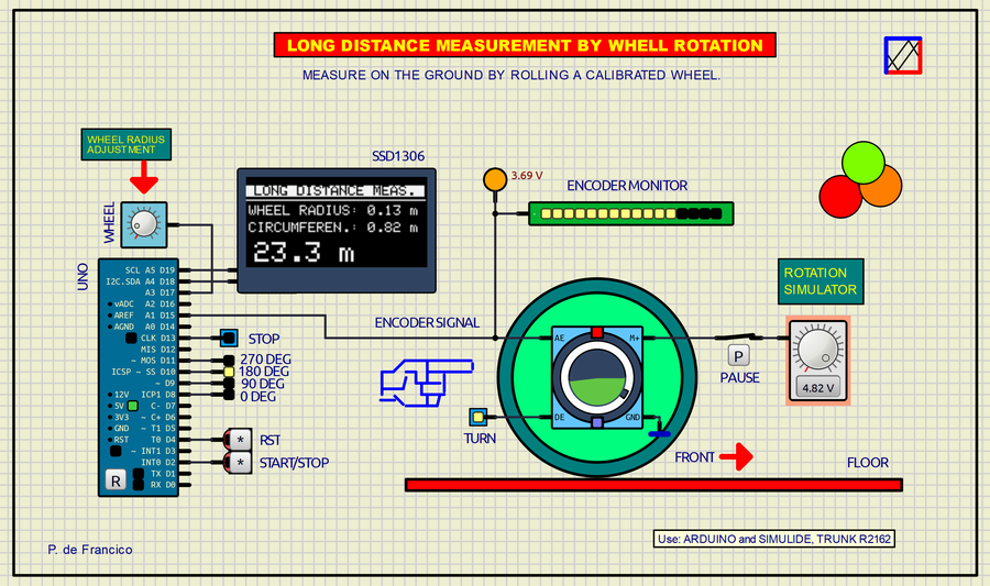
- [START/STOP]: In STOP the radio is adjusted and the odometer data in meters can also be deleted and the <STOP> LED flashes continuously. In START the measurement starts. The wheel will rotate if the <PAUSE> switch and the power supply have a voltage between 0 and 5 volts to simulate the measurement speed. In this position the radio can no longer be adjusted and the <STOP> LED turns off. The degree LEDs will begin to move at the rate of rotation of the measuring wheel marking each of the quarters of the wheel where the measurement is taken, these ranges are: 0 to 89 degrees, 90 to 179, 180 to 269 and 270 to 359
- [RESET] In STOP mode the odometer counter can be reset.
- ADJUSTMENT POTENTIOMETER. In STOP mode, the wheel radius can be adjusted from 0 to 0.99 meters. The data is displayed on the OLED.
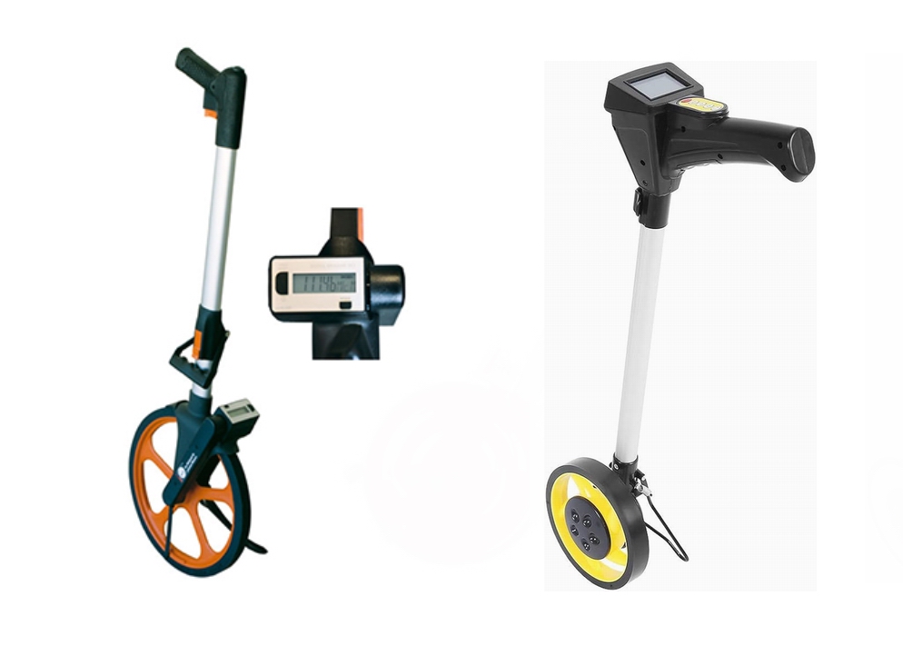
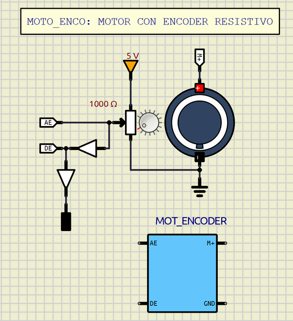
- MEASURING WHEEL: It is associated with the motor shaft that moves the potentiometer of the internal encoder of the DC motor.
To know more about the odometer: https://es.wikipedia.org/wiki/Od%C3%B3metro
SCHEME:
The project is based on Arduino UNO as a controller. The 128×64-bit monochrome OLED display is connected via I2C. The [RST] and [START/STOP] buttons are connected to D4 and D2 respectively with internal PULLUP. The set of LEDs used as a monitor are connected as shown in the diagram and calculated for a current of about 20mA each. The <WHELL> potentiometer provides a regulated voltage between 0 and 5V through input A3. Through A1, the DC-motor encoder voltage from 0 to 5v is entered. The ENCODER-MONITOR is a complementary encoder position information device. The power supply and the <PAUSE> switch make up the rotation simulation stage, introducing a voltage of 0 to 5V to the motor to simulate the rotation speed of the wheel and therefore the measurement. This speed does not affect the measurement result, nor even its potential variations.
PROGRAM:
// LONG DISTANCE METER BY WHELL ROTATION (Odometer). DEFRAN24
// Use Arduino and Simulide R2162.
#include <Wire.h>
#include <Adafruit_GFX.h>
#include <Adafruit_SSD1306.h>
#define SCREEN_WIDTH 128
#define SCREEN_HEIGHT 64
Adafruit_SSD1306 display(SCREEN_WIDTH, SCREEN_HEIGHT, &Wire, -1);
int MON=13;
int G1=8, G2=9, G3=10, G4=11;
int MEAS=2;
int RST=4;
int senV;
int dista=A1; // ENCODER SENSOR
int Wheel=A3; // RADIUS POTENTIOMETER
int v1, v2, v3, v4;
float radius=0;
float rota=0;
float ruedaR;
float circun;
float rueda4;
int state=HIGH;
int MEASv;
void setup()
{
pinMode(MEAS, INPUT_PULLUP);
pinMode(RST, INPUT_PULLUP);
pinMode(MON, OUTPUT);
pinMode(G1, OUTPUT); pinMode(G2, OUTPUT); pinMode(G3, OUTPUT); pinMode(G4, OUTPUT);
if(!display.begin(SSD1306_SWITCHCAPVCC, 0x3C)) {for(;;);} // Address 0x3C
display.cp437(true);
display.clearDisplay();
attachInterrupt(digitalPinToInterrupt(MEAS), RUPTO, RISING); // Interruption
MEASv=LOW;
}
void loop()
{
FLA:
if (MEASv==LOW) // ADJUSTMENT CALCULATION
{
senV=0;
ruedaR=analogRead(Wheel); // V. analog from encoder
ruedaR=map(ruedaR, 0, 1023, 0, 100); // Scale (0 to 100)
radius=ruedaR/100; // Radius
circun=radius*2*3.14; // Circumference
rueda4=circun/4; // Circumference /4
OLED();
digitalWrite(MON,HIGH); delay(200); digitalWrite(MON,LOW); delay(50);
if(digitalRead(RST)==HIGH) {senV=0; rota=0; OLED();} // RESET
goto FLA;
}
do {senV=analogRead(dista); digitalWrite(G1,HIGH); v1=senV;} // UP
while (senV>0 && senV<224); // RANGE
digitalWrite(G1,LOW); // LED
if (v1>v4) rota=rota+rueda4; // DIRECTION
OLED();
do {senV=analogRead(dista); digitalWrite(G2,HIGH); v2=senV;} // LEFT
while (senV>225 && senV<511);
digitalWrite(G2,LOW);
if (v2>v1) rota=rota+rueda4;
OLED();
do {senV=analogRead(dista); digitalWrite(G3,HIGH); v3=senV;} // RIGHT
while (senV>512 && senV<767);
digitalWrite(G3,LOW);
if (v3>v2) rota=rota+rueda4;
OLED();
do {senV=analogRead(dista); digitalWrite(G4,HIGH); v4=senV;} // DOWN
while (senV>768 && senV<1023);
digitalWrite(G4,LOW);
if (v3>v4) rota=rota+rueda4;
OLED();
}
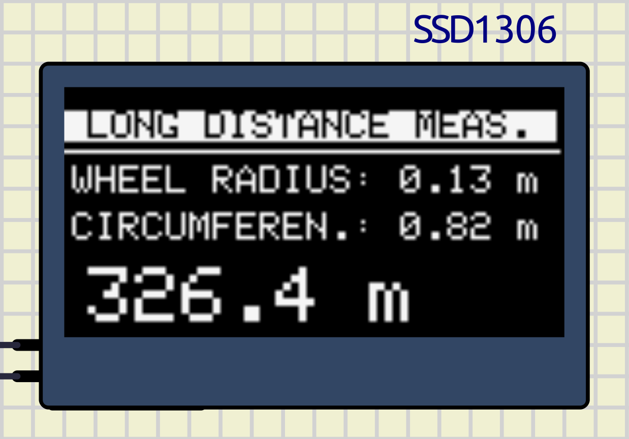
void OLED()
{
display.clearDisplay();
display.setTextSize(1); // Size 1
display.setTextColor(BLACK, WHITE); // White background
display.setCursor(0, 6);
display.print(" LONG DISTANCE MEAS. ");
display.setTextColor(WHITE);
display.drawLine(0,16,126,16,WHITE); // LINE X,Y,WIDTH, Y FIN
display.setCursor(2, 20);
display.print("WHEEL RADIUS: ");
display.print(radius); // Radius
display.print(" m");
display.setCursor(2, 32);
display.print("CIRCUMFEREN.: ");
display.print(circun); // Circumference
display.print(" m");
display.setTextSize(2); // Size 2
display.setCursor(6, 46);
display.print(rota,1); // Distance
display.print(" m");
display.display();
}
void RUPTO()
{
state=!state; if (state==LOW) MEASv=LOW; else MEASv=HIGH; // Interruption
}MISCELLANY.
The attached zip file typically includes:
- Electrical diagram.
- Program.
- “data” subcircuits folder.
This data folder contains the subcircuits (custom) created by the author. The presence of this folder is necessary for the execution of the project.
 DC-MOTOR and linear encoder.