GUESS LED GAME__(DF328)
PURPOSE.
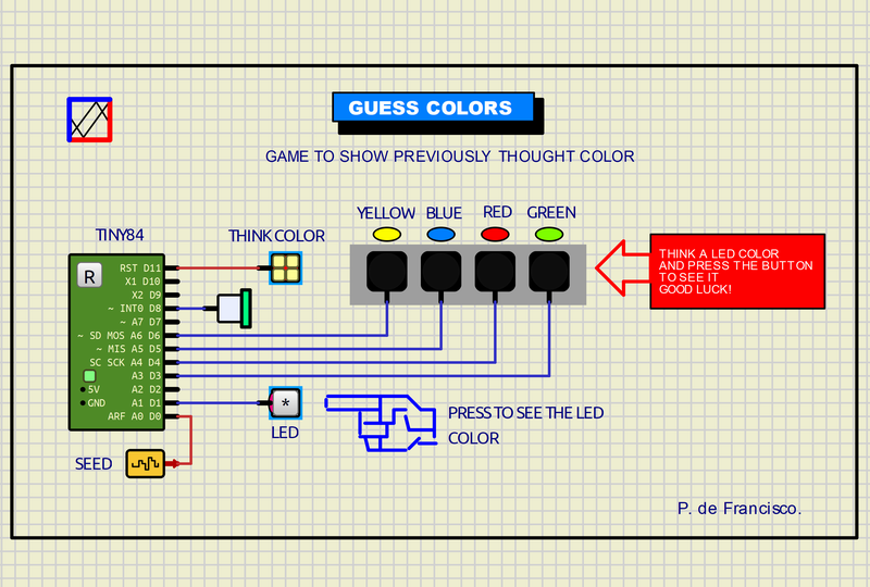
Game consisting of guessing the color of the LED that will light up after pressing the button.
USE.
When starting the program the “THINK COLOR” LED flashes, think of one of the four colors. Then press the button, the randomly generated LED number lights up for a few seconds and a small warning beep sounds. The player will determine if he was correct or not.
DIAGRAM.
The controller is the ATTiny84. There are 4 LEDs of YELLOW, BLUE, RED AND GREEN colors connected to the Tiny84.
Another yellow “THINK COLOR” LED at D11, a speaker at 8, the trigger button at D1.
A low frequency randomness seed oscillator at A0.
PROGRAM.
The source program and the executable are included. The C program is responsible for managing all the LEDs and the sound.
When starting the program, the “THINK COLOR” LED flashes regularly in millis mode (instead of delay) so that the program sequence does not interfere with its flashing. In this indeterminate time the player has to think of one of the four colors.
When you press the button, the number of one of the four colored LEDs is generated, which then illuminates it for a few seconds, turning off the previous LED. From here the sequence repeats.
The randomness seed is obtained by A0. The randomization instruction: led=random(3, 7) to manage the 4 leds and the sound with: tone(beep, 1000, 60) where “beep” is the port, 1000 is the tone and 60 is the time in milliseconds.
IMPORTANT do not forget to configure Simulide for ATTiny84 if the program is compiled.
MISCELLANY.
The attached zip file typically includes:
1) Electrical diagram.
2) Source program.
3) Executable.
4) “data” folder.
This data folder contains the subcircuits (custom) created by the author. The presence of this folder is necessary for the execution of the project.
SUBCIRCUIT: It is a “custom” circuit that accumulates a set of Simulide base components to obtain a new or an adapted function. These subcircuits are treated by Simulide as another component of its own structure.
Subcircuits are very useful to create a component that does not exist in the simulide set, to compress a complete schematic in a single block and thus improve the complexity and compression of the final circuit where it is integrated or for any other function that you want to have available when making a schematic.
The subcircuits must be properly incorporated in the “data” folder of simulide, in the “User Data” folder or in the “data” scheme folder that must be attached together with the schematic of the project itself. Attaching the subcircuits to the Simulide “data” folder is not advisable because they can be lost with updates to it. Attaching them in “User Data” is the correct thing to do. Attaching it to the “data” folder of the diagram is necessary when it is shared.
Creating and locating a subcircuit is simple once you know the procedure that is explained in detail in the simulide tutorials: