Digital Audio Sinewave Generator Based on Delta Modulation
Quote from KerimF on November 26, 2024, 10:48 amIt is about a digital audio sinewave generator from 20 Hz to 20 KHz.
It is based on digital delta modulation. So, if the bit rate is made to be high (2 MHz, 100 times 20 KHz), a non-critical low pass filter (even a passive 3-pole RC LPF, for example) can recover the sinewave with a low THD. The MCU is ATmega32A (the one I can get) and the generated delta bit stream is outputted at its PB.7 pin.
With an 8 MHz crystal, a frequency from 20833 Hz down to 647.67 Hz (the high band) could be selected. Its index is from 0 to 484 (485 frequencies). Also, a frequency from 651.04 Hz down to 20.240 Hz (the low band) could be selected. Its index is from 485 to 969 (another 485 frequencies, total 970).
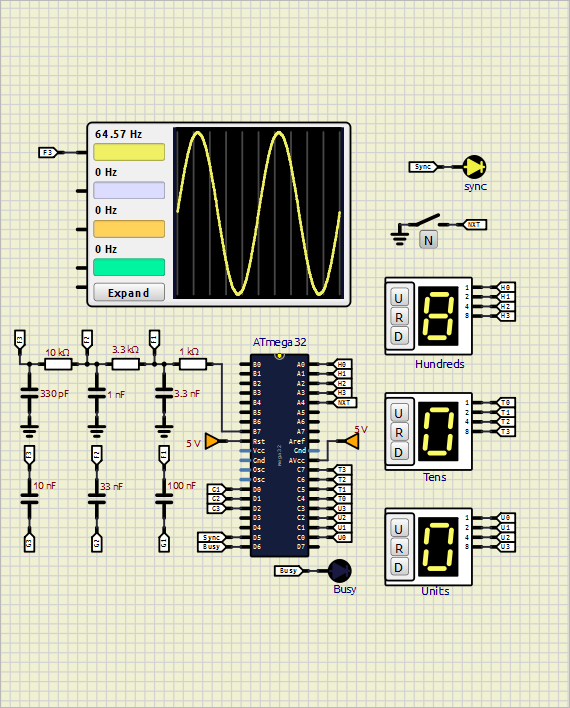
Thanks to simulIDE, it was possible for me to fix many bugs in my rather complex code. In my experimental circuit I used 3-RC LPF. And to input the frequency index (0 to 969), I used 3 encoded BCD 10-state thumbwheels. The scope displays the sinewaves of the low band (index 485 up to 969) though, for a few of them, with a small distortion. Such distortion doesn’t exist in real. I mean that the scope of simulIDE is ok for the low band only because the delta bit rate is 62,500 Hz, not 2,000,000 Hz (of the high band).
I am not sure if this project is suitable or not to be uploaded here (and discussed perhaps). If it is, I will prepare all its relevant files for upload. Otherwise, it will be better to delete this 1-post topic.
Kerim
It is about a digital audio sinewave generator from 20 Hz to 20 KHz.
It is based on digital delta modulation. So, if the bit rate is made to be high (2 MHz, 100 times 20 KHz), a non-critical low pass filter (even a passive 3-pole RC LPF, for example) can recover the sinewave with a low THD. The MCU is ATmega32A (the one I can get) and the generated delta bit stream is outputted at its PB.7 pin.
With an 8 MHz crystal, a frequency from 20833 Hz down to 647.67 Hz (the high band) could be selected. Its index is from 0 to 484 (485 frequencies). Also, a frequency from 651.04 Hz down to 20.240 Hz (the low band) could be selected. Its index is from 485 to 969 (another 485 frequencies, total 970).
Thanks to simulIDE, it was possible for me to fix many bugs in my rather complex code. In my experimental circuit I used 3-RC LPF. And to input the frequency index (0 to 969), I used 3 encoded BCD 10-state thumbwheels. The scope displays the sinewaves of the low band (index 485 up to 969) though, for a few of them, with a small distortion. Such distortion doesn’t exist in real. I mean that the scope of simulIDE is ok for the low band only because the delta bit rate is 62,500 Hz, not 2,000,000 Hz (of the high band).
I am not sure if this project is suitable or not to be uploaded here (and discussed perhaps). If it is, I will prepare all its relevant files for upload. Otherwise, it will be better to delete this 1-post topic.
Kerim
Quote from arcachofo on November 26, 2024, 12:31 pmSuch distortion doesn’t exist in real. I mean that the scope of simulIDE is ok for the low band only because the delta bit rate is 62,500 Hz, not 2,000,000 Hz (of the high band).
The Oscilloscope should be ok upto hundreds of GHz.
I think it is only showing what is happening in the simulation.Maybe you should have a look at "Reactive Step" for those capacitors:
https://simulide.com/p/reactive-components/
Such distortion doesn’t exist in real. I mean that the scope of simulIDE is ok for the low band only because the delta bit rate is 62,500 Hz, not 2,000,000 Hz (of the high band).
The Oscilloscope should be ok upto hundreds of GHz.
I think it is only showing what is happening in the simulation.
Maybe you should have a look at "Reactive Step" for those capacitors:
https://simulide.com/p/reactive-components/
Quote from KerimF on November 26, 2024, 5:41 pmQuote from arcachofo on November 26, 2024, 12:31 pmSuch distortion doesn’t exist in real. I mean that the scope of simulIDE is ok for the low band only because the delta bit rate is 62,500 Hz, not 2,000,000 Hz (of the high band).
Maybe you should have a look at "Reactive Step" for those capacitors:
https://simulide.com/p/reactive-components/I am now preparing the files for upload so that you can verify how it works on your side and find out how the scope can also display the sinewaves of the high band.
For instance, the same delta bit streams (485 ones) of the low band are used for the high band. Only the bit rate is made higher (2 MHz instead of 62.5 KHz). For the high band (index 0 to 484), the period of the code loop is 4 MCU cycles only (8 MHz / 4 = 2 MHz).
As you will see, the bits of every stream are saved in the SRAM space, at the start address 0x06B8, before being read by the wave loop.
During the design (many months, since I started the project from scratch), I used Excel to also plot the integral (digital, 1's and 0's) of these bits (one cycle) to see how their waveform looks like before filtering. For instance, I chose the number of bits per cycle to be 96 (band's highest frequency) up to 3088 (band's lowest frequency). When the bits per cycle are relatively big, their Excel plot shows a clean sinewave. On request, I will also upload the Excel sheets which accept the SRAM data (bytes from 0x06B8, after saved by simulIDE) to plot the waveform. I said 'sheets' not 'sheet', because bits are saved as bytes. So, when mod(Nbits, 8) is not zero (Nbits=bits per cycle), there are extra bits to take care of separately at the beginning. Also, if Nbits is odd, the bit stream should be made for two cycles instead of one, since the sum of the stream bits has to be zero.
Anyway, let us start with step 1... uploading the generator's files. See you soon.
Kerim
Quote from arcachofo on November 26, 2024, 12:31 pmSuch distortion doesn’t exist in real. I mean that the scope of simulIDE is ok for the low band only because the delta bit rate is 62,500 Hz, not 2,000,000 Hz (of the high band).
Maybe you should have a look at "Reactive Step" for those capacitors:
https://simulide.com/p/reactive-components/
I am now preparing the files for upload so that you can verify how it works on your side and find out how the scope can also display the sinewaves of the high band.
For instance, the same delta bit streams (485 ones) of the low band are used for the high band. Only the bit rate is made higher (2 MHz instead of 62.5 KHz). For the high band (index 0 to 484), the period of the code loop is 4 MCU cycles only (8 MHz / 4 = 2 MHz).
As you will see, the bits of every stream are saved in the SRAM space, at the start address 0x06B8, before being read by the wave loop.
During the design (many months, since I started the project from scratch), I used Excel to also plot the integral (digital, 1's and 0's) of these bits (one cycle) to see how their waveform looks like before filtering. For instance, I chose the number of bits per cycle to be 96 (band's highest frequency) up to 3088 (band's lowest frequency). When the bits per cycle are relatively big, their Excel plot shows a clean sinewave. On request, I will also upload the Excel sheets which accept the SRAM data (bytes from 0x06B8, after saved by simulIDE) to plot the waveform. I said 'sheets' not 'sheet', because bits are saved as bytes. So, when mod(Nbits, 8) is not zero (Nbits=bits per cycle), there are extra bits to take care of separately at the beginning. Also, if Nbits is odd, the bit stream should be made for two cycles instead of one, since the sum of the stream bits has to be zero.
Anyway, let us start with step 1... uploading the generator's files. See you soon.
Kerim
Quote from KerimF on November 27, 2024, 5:38 am
I attached the files of the audio generator, DSSaudioGenerator_v1.zip.
DSS here means ‘Delta Sinewave Synthesis’. But I noticed that it may also mean ‘Digital Sinewave Synthesis’.
It includes:
DSSaudioGenerator_v1.asm
DSSaudioGenerator_v1.hex
DSSaudioGenerator_v1.lst
DSSaudioGenerator_v1.sim1
DSS_frequencies_v1.txtTo simulate it, the switch [N] needs to be closed first, if it is not closed already. Otherwise, the frequency index would be 000 which is of the highest frequency of the high band, 20,833 Hz.
Then, the debugger can be started. And while the simulation is running, the desired frequency index on the 3 thumbwheels can be set.
When the switch will be opened, a sinewave will be seen on the scope if its frequency is relatively low (whose frequency index is 800 or 900, for example).
Every time the switch is closed and reopened, a new frequency will be displayed if the frequency index was changed.
Please don’t hesitate to ask or comment about anything related to this DSS project.
Kerim
I attached the files of the audio generator, DSSaudioGenerator_v1.zip.
DSS here means ‘Delta Sinewave Synthesis’. But I noticed that it may also mean ‘Digital Sinewave Synthesis’.
It includes:
DSSaudioGenerator_v1.asm
DSSaudioGenerator_v1.hex
DSSaudioGenerator_v1.lst
DSSaudioGenerator_v1.sim1
DSS_frequencies_v1.txt
To simulate it, the switch [N] needs to be closed first, if it is not closed already. Otherwise, the frequency index would be 000 which is of the highest frequency of the high band, 20,833 Hz.
Then, the debugger can be started. And while the simulation is running, the desired frequency index on the 3 thumbwheels can be set.
When the switch will be opened, a sinewave will be seen on the scope if its frequency is relatively low (whose frequency index is 800 or 900, for example).
Every time the switch is closed and reopened, a new frequency will be displayed if the frequency index was changed.
Please don’t hesitate to ask or comment about anything related to this DSS project.
Kerim
Uploaded files:
Quote from KerimF on November 27, 2024, 11:59 amQuote from arcachofo on November 27, 2024, 8:11 amNice project.
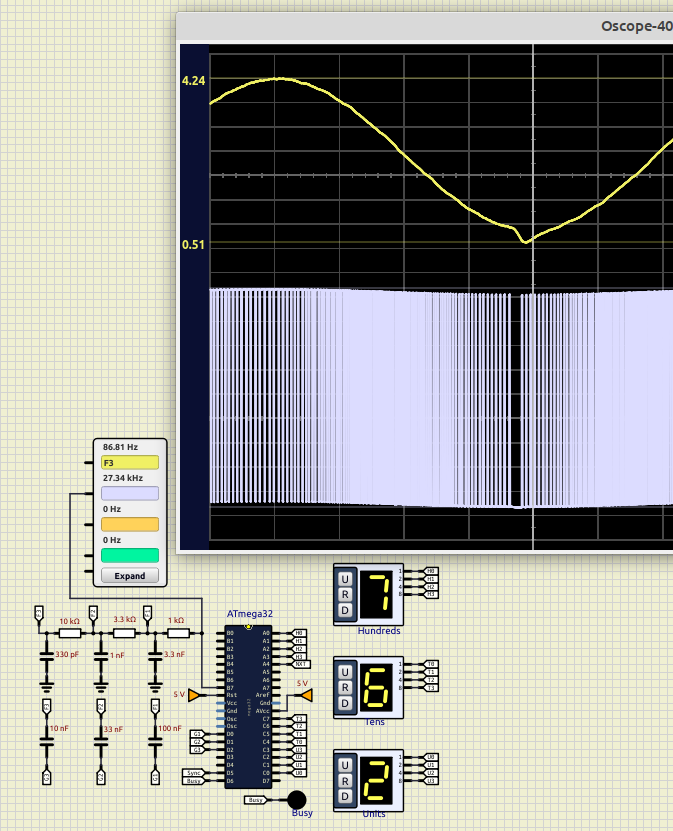
Is this the distortion you mentioned?
No.
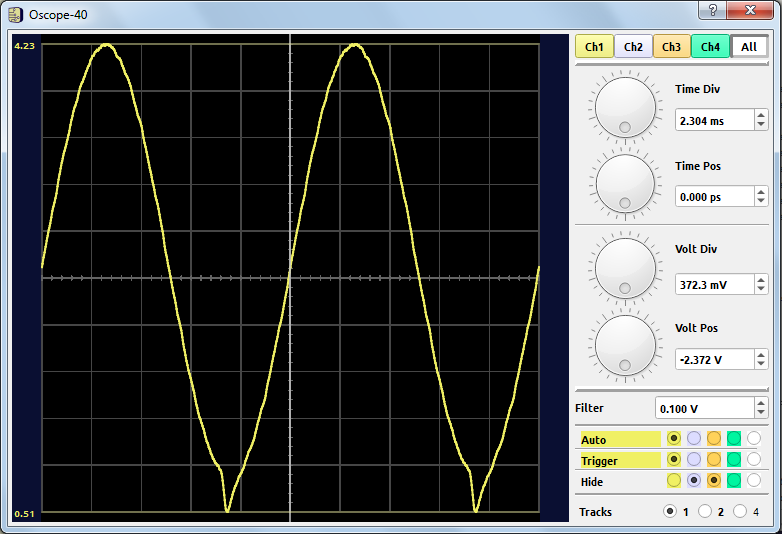
The distortion I was referring to occurs at some low frequencies (low band). It occurs at the negative peak only.
I found now some of these frequencies. Their indexes are:
762, 752, 772, 683 and 685.
The worst one is of 762 (attached)
Quote from arcachofo on November 27, 2024, 8:11 amNice project.
Is this the distortion you mentioned?
No.
The distortion I was referring to occurs at some low frequencies (low band). It occurs at the negative peak only.
I found now some of these frequencies. Their indexes are:
762, 752, 772, 683 and 685.
The worst one is of 762 (attached)
Quote from KerimF on November 27, 2024, 2:38 pmI will check the bits of this stream (stored in SRAM) on Excel to see if it is also missing a pulse or more.
And I think it is time for me to check each frequency on a real board too.
Thank you.
I will check the bits of this stream (stored in SRAM) on Excel to see if it is also missing a pulse or more.
And I think it is time for me to check each frequency on a real board too.
Thank you.
Quote from KerimF on November 27, 2024, 3:18 pmIt seems that the generated stream in SRAM is ok. But perhaps there is still a hidden bug in the wave loop that reads its bits.
I will have a look.
I also attached the bits per cycle of each index (and the frequency), DSS_Bits_Frequencies_v1.zip.
It seems that the generated stream in SRAM is ok. But perhaps there is still a hidden bug in the wave loop that reads its bits.
I will have a look.
I also attached the bits per cycle of each index (and the frequency), DSS_Bits_Frequencies_v1.zip.
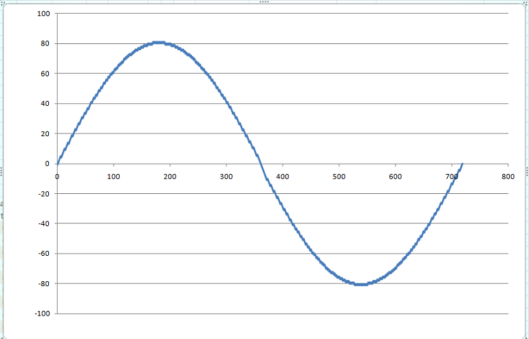
Quote from KerimF on November 27, 2024, 6:02 pmI attached the Excel sheet of index 762, SinePlot_DSS_762_v1.zip
The bytes at the cells T53, T54 and T55 (dark orange color) give the 17 consecutive 0’s. See also the cells of 0's at P365 to P381.
These 0’s are actually at the zero crossing of the sinewave (negative slope). But the 3-RC LPF shifts its phase.
I attached the Excel sheet of index 762, SinePlot_DSS_762_v1.zip
The bytes at the cells T53, T54 and T55 (dark orange color) give the 17 consecutive 0’s. See also the cells of 0's at P365 to P381.
These 0’s are actually at the zero crossing of the sinewave (negative slope). But the 3-RC LPF shifts its phase.
Uploaded files:
