
Forum breadcrumbs - You are here:ForumGeneral: Circuits and examples made in SimulIDE352__LITHIUM ION BATTERY CHARGER
You need to log in to create posts and topics.
352__LITHIUM ION BATTERY CHARGER
Defran@defran
128 Posts
#1 · January 29, 2024, 9:04 pm
Quote from Defran on January 29, 2024, 9:04 pm
352__LITHIUM ION BATTERY CHARGER. (Simulide R2162 or higher)
The purpose of this example is to make a lithium battery charger with automatic disconnection when charging is finished. The type of batteries provided is the 1.5V "AA" type, although others can be used by adjusting values in the potentiometers. Charging starts automatically when the battery is inserted or by pressing the [CHARGE] button if the system is in "END".It has two potentiometers: current limit adjustment (100mA or less) and voltage limit adjustment (8V or less). With the current one, the maximum charging current is adjusted and with the voltage one, the voltage value considered for a charged battery is adjusted. When this value is reached, the supply voltage to the charging circuit is cut off, the "CHARGE" LED turns off and "END" turns on flashing.To simulate the charging behavior of the battery, start by placing the "BATTERY SIMULATION" potentiometer at the lower point (EMPTY), here the maximum value of charging current will be adjusted with the "CURRENT LIMIT" potentiometer, then gradually increase the value of the "VOLTAGE LIMIT" potentiomer until reaching the maximum voltage value for the inserted battery (This value must be above the nominal value of the battery for charging to occur) Upon reaching this voltage the stop circuit will operate and The "END" LED will light up. To start a new cycle insert the battery and press [CHARGE].SCHEME:The heart of the circuit is based on the LM317 regulator, in current control configuration, adjustable with the "CURRENT LIMIT" potentiometer. The battery to be charged receives power from the emitter of the BD139 transistor and with the ammeter in series and voltmeter in parallel, the charge values are displayed. The rest of the scheme is to obtain the cut-off control of the charging circuit once the charge has been reached. This cut-off is obtained with the BD137 transistor, in turn controlled by the 4027 flip-flop in RS configuration. The "CHARGE" and "END" LEDs at their outputs monitor the status of the charger. The reset input of the flip-flop has an associated autoreset circuit in the connection and the [CHARGE] button that does the same effect manually. The flip-flop clock input is connected to the LM324 comparator whose output, when it goes HIGH as a result of the battery voltage rise, changes its state. The reference value is adjusted with the "VOLTAGE LIMIT" potentiometer. The <+> input of the comparator is connected to the battery from which it takes the sample.To know more about the LM317 regulator: file:///C:/Users/primy/Downloads/LM317.PDFSUBCIRCUITS:This example integrates several subcircuits located in the "data" folder into the ZIP attached. This folder must always be next to the "sim1" scheme so that it can be executed. A subcircuit is a “custom” circuit that accumulates a set of Simulide base components (primitive function) to obtain a new or an adapted function. These subcircuits are treated by Simulide as another component of its own structure. User can create his own subcircuits or use the ones published here in your own designs once the procedure is known, explained in detail in the Simulide tutorials: https://simulide.com/p/subcircuits/* Communication with the author: Simulide/User/Messages/DefranP. de Francisco.
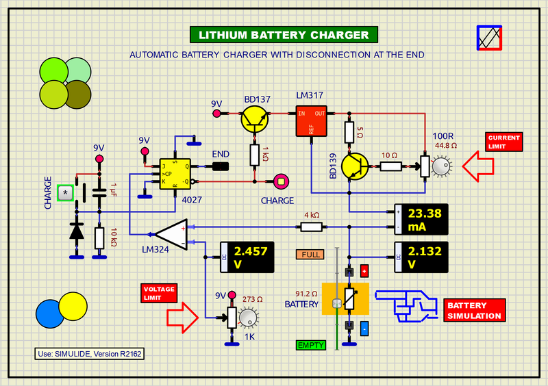
352__LITHIUM ION BATTERY CHARGER. (Simulide R2162 or higher)
The purpose of this example is to make a lithium battery charger with automatic disconnection when charging is finished. The type of batteries provided is the 1.5V "AA" type, although others can be used by adjusting values in the potentiometers. Charging starts automatically when the battery is inserted or by pressing the [CHARGE] button if the system is in "END".
It has two potentiometers: current limit adjustment (100mA or less) and voltage limit adjustment (8V or less). With the current one, the maximum charging current is adjusted and with the voltage one, the voltage value considered for a charged battery is adjusted. When this value is reached, the supply voltage to the charging circuit is cut off, the "CHARGE" LED turns off and "END" turns on flashing.
To simulate the charging behavior of the battery, start by placing the "BATTERY SIMULATION" potentiometer at the lower point (EMPTY), here the maximum value of charging current will be adjusted with the "CURRENT LIMIT" potentiometer, then gradually increase the value of the "VOLTAGE LIMIT" potentiomer until reaching the maximum voltage value for the inserted battery (This value must be above the nominal value of the battery for charging to occur) Upon reaching this voltage the stop circuit will operate and The "END" LED will light up. To start a new cycle insert the battery and press [CHARGE].
SCHEME:
The heart of the circuit is based on the LM317 regulator, in current control configuration, adjustable with the "CURRENT LIMIT" potentiometer. The battery to be charged receives power from the emitter of the BD139 transistor and with the ammeter in series and voltmeter in parallel, the charge values are displayed. The rest of the scheme is to obtain the cut-off control of the charging circuit once the charge has been reached. This cut-off is obtained with the BD137 transistor, in turn controlled by the 4027 flip-flop in RS configuration. The "CHARGE" and "END" LEDs at their outputs monitor the status of the charger. The reset input of the flip-flop has an associated autoreset circuit in the connection and the [CHARGE] button that does the same effect manually. The flip-flop clock input is connected to the LM324 comparator whose output, when it goes HIGH as a result of the battery voltage rise, changes its state. The reference value is adjusted with the "VOLTAGE LIMIT" potentiometer. The <+> input of the comparator is connected to the battery from which it takes the sample.
To know more about the LM317 regulator: file:///C:/Users/primy/Downloads/LM317.PDF
SUBCIRCUITS:
This example integrates several subcircuits located in the "data" folder into the ZIP attached. This folder must always be next to the "sim1" scheme so that it can be executed. A subcircuit is a “custom” circuit that accumulates a set of Simulide base components (primitive function) to obtain a new or an adapted function. These subcircuits are treated by Simulide as another component of its own structure. User can create his own subcircuits or use the ones published here in your own designs once the procedure is known, explained in detail in the Simulide tutorials: https://simulide.com/p/subcircuits/
* Communication with the author: Simulide/User/Messages/Defran
P. de Francisco.
Click for thumbs down.0Click for thumbs up.0
Last edited on March 17, 2024, 9:47 pm by Defran