SERVO CONTROLLED BY KEYBOARD__(DF330)
PURPOSE.
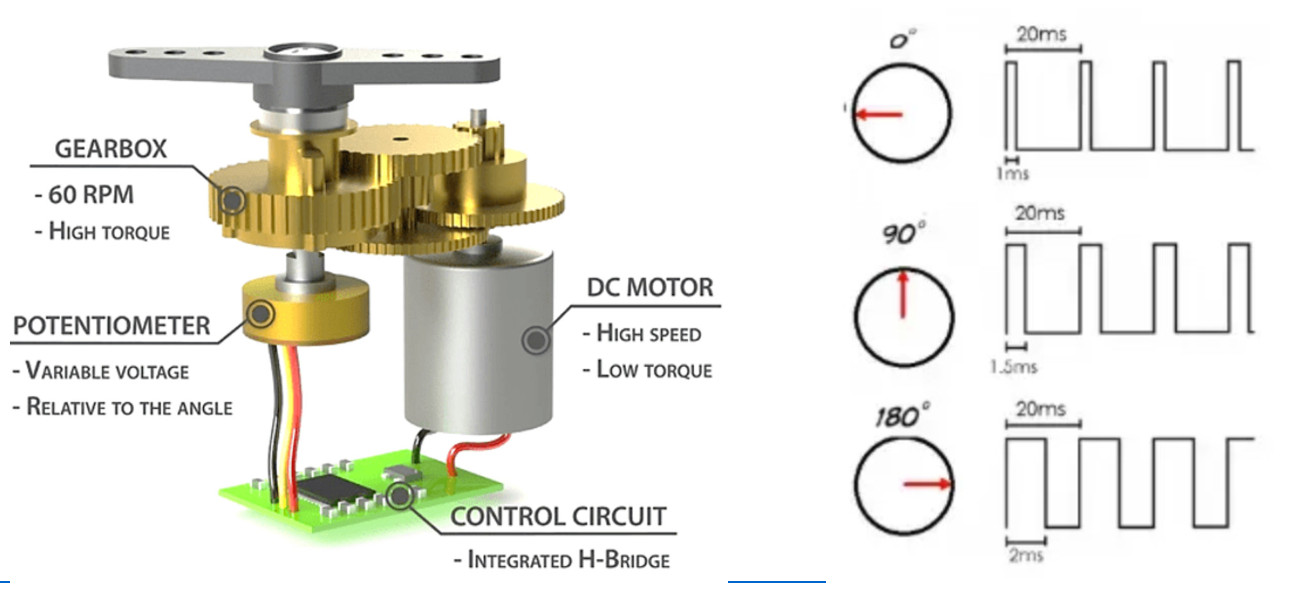
The goal of this project is to control a servomotor by entering the degrees of rotor rotation between 0 and 180 degrees using a numeric keypad. Useful for practicing with this type of motors as well as their adjustment in Simulide. Servomotor or simply SERVO. Summary A servomotor (also called a servo) is a device capable of moving the rotor to a certain angle, typically from 0 to 180 degrees and remaining stable in that position, although there are also up to 360 degrees. They are characterized by their speed, low inertia and low consumption. A servo is essentially composed of a DC motor, control electronics (microcontroller and divers), a potentiometer connected to the motor shaft (acting as an encoder to know the position of the rotor) and a mechanical system made up of gears to regulate the speed and the turning power (torque). The Servo is controlled by pulses sent one every 20ms (50Hz). The pulse width determines the rotation angle (PWM), usually between 0.5 and 2.5 ms
It has its application in devices that need perfect control of the mechanics they move, such as in robotics, model airplanes, etc. Widely used in the world of makers.
USE.
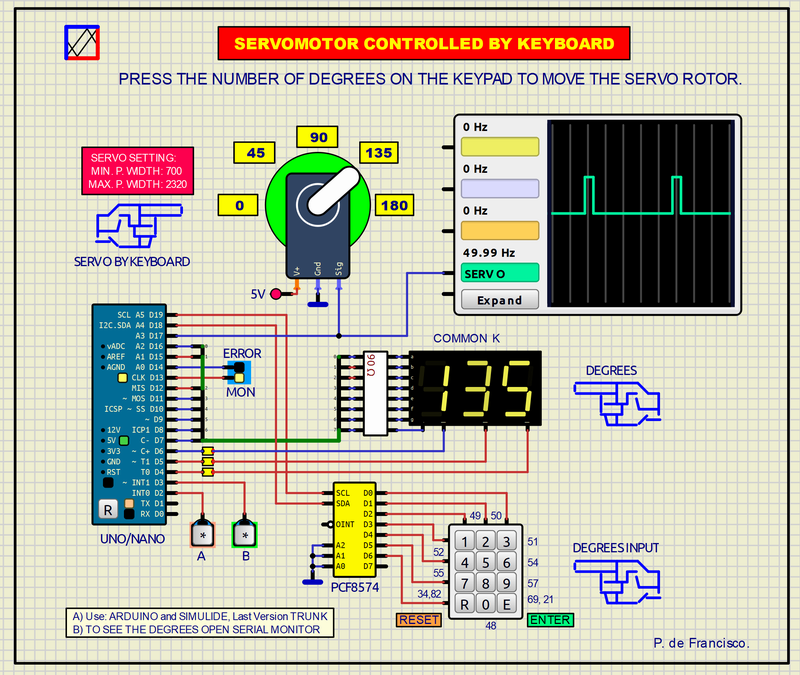
 Enter the value in degrees that will appear on the 7-segment display (<R> Deletes the value if there is a typing error). Now press <E> ENTER so that the rotor moves according to the number of degrees entered to the corresponding position. The “MON” (Monitor) LED turns on when the operation is completed and turns off at the beginning of a new one. Repeat with another value and so on.
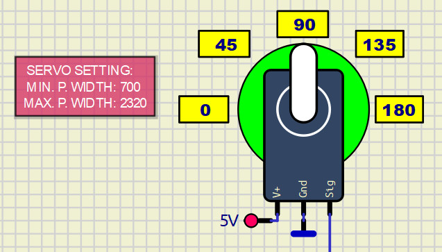 The positioning accuracy of the rotor depends on the servo settings, the adjustment of which is done in “properties”. The red label shows an approximation of values that the user can modify. <R> RESET can be used at any time to correct the quantity or to bring the rotor to the zero position. If a value greater than 180 is entered, the error LED turns on. The pulse width for each value and the distance between pulses are displayed on the oscilloscope.
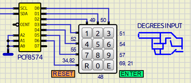
SCHEMATIC.
PROGRAM.
The source program and the executable are included. Two libraries are used that must be previously installed in the Arduino IDE if this program is compiled: #include <Wire.h> #include <Keypad_I2C.h> #include <Servo.h> The program is not particularly complex and the commands required by the libraries are used. By opening the Serial Monitor you can also see the number of degrees entered.
MISCELLANY.
The attached zip file typically includes: 1) Electrical diagram. 2) Source program. 3) Executable. 4) “data” folder. This data folder contains the subcircuits (custom) created by the author. The presence of this folder is necessary for the execution of the project. SUBCIRCUIT: It is a “custom” circuit that accumulates a set of Simulide base components to obtain a new or an adapted function. These subcircuits are treated by Simulide as another component of its own structure.
Subcircuits are very useful to create a component that does not exist in the simulide set, to compress a complete schematic in a single block and thus improve the complexity and compression of the final circuit where it is integrated or for any other function that you want to have available when making a schematic.
The subcircuits must be properly incorporated in the “data” folder of simulide, in the “User Data” folder or in the “data” scheme folder that must be attached together with the schematic of the project itself. Attaching the subcircuits to the Simulide “data” folder is not advisable because they can be lost with updates to it. Attaching them in “User Data” is the correct thing to do. Attaching it to the “data” folder of the diagram is necessary when it is shared.
Creating and locating a subcircuit is simple once you know the procedure that is explained in detail in the simulide tutorials: https://simulide.com/p/subcircuits/
RESOURCES.
PCF8574. SERVO Concept
SERVO Motor operation.