
Transformer voltages
Quote from KerimF on January 29, 2024, 2:51 pmSimulIDE-R2116_Win32
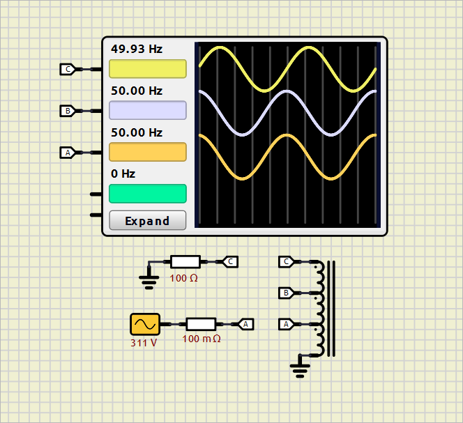
I tried to simulate a circuit which has a transformer having three coils in series. Their turns are 93, 32 and 53 respectively.
I surely miss something on the schematic since the voltages on its upper two terminals B and C are wrong.
Thank you.
SimulIDE-R2116_Win32
I tried to simulate a circuit which has a transformer having three coils in series. Their turns are 93, 32 and 53 respectively.
I surely miss something on the schematic since the voltages on its upper two terminals B and C are wrong.
Thank you.
Quote from KerimF on January 30, 2024, 8:52 amQuote from arcachofo on January 29, 2024, 3:29 pmHi.
Which voltages do you expect?Hi,
The turns are:
93 from ground to A
32 from A to B
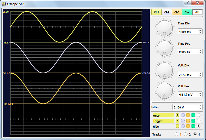
53 from B to CIf V(A) =311 (220 Vrms), I expected (as Vpeak):
V(B) = 311 * (93+32)/93 = 418 V
V(C) = 311 * (93+32+53)/93 = 595 VOn my side, I got:
Quote from arcachofo on January 29, 2024, 3:29 pmHi.
Which voltages do you expect?
Hi,
The turns are:
93 from ground to A
32 from A to B
53 from B to C
If V(A) =311 (220 Vrms), I expected (as Vpeak):
V(B) = 311 * (93+32)/93 = 418 V
V(C) = 311 * (93+32+53)/93 = 595 V
On my side, I got:
Quote from arcachofo on January 30, 2024, 3:22 pmAs I see in the configuration for the transformer, turns are 92,32,53:
C-B = 92
B-A = 32
A-GND = 53And (C) is connected to ground through a 100 Ohm resistor, so the voltage here is expected to be very low.
The turns are:
93 from ground to A
32 from A to B
53 from B to CTo get the values you expect yo should use:
-Transformer: Primary = 53,32,93
-Disconnect (C) from ground.
I see a potential problem with transformers:
If the component is rotated then then the order could be different.
Same if it is flipped for Primary/Secondary.
We need some kind of marker for the first coil and also for Primary/Secondary.
As I see in the configuration for the transformer, turns are 92,32,53:
C-B = 92
B-A = 32
A-GND = 53
And (C) is connected to ground through a 100 Ohm resistor, so the voltage here is expected to be very low.
The turns are:
93 from ground to A
32 from A to B
53 from B to C
To get the values you expect yo should use:
-Transformer: Primary = 53,32,93
-Disconnect (C) from ground.
I see a potential problem with transformers:
If the component is rotated then then the order could be different.
Same if it is flipped for Primary/Secondary.
We need some kind of marker for the first coil and also for Primary/Secondary.
Quote from KerimF on January 30, 2024, 4:50 pmQuote from arcachofo on January 30, 2024, 3:22 pmAs I see in the configuration for the transformer, turns are 92,32,53:
C-B = 92
B-A = 32
A-GND = 53And (C) is connected to ground through a 100 Ohm resistor, so the voltage here is expected to be very low.
To get the values you expect you should use:
-Transformer: Primary = 53,32,93
-Disconnect (C) from ground.
I followed what you said and the voltages at (A), (B) and (C) became as expected after disconnecting (C) from ground.
For the time being in the least, re-organizing the values of turns to get the right voltages could be done whenever necessary.
For instance, I guess the transformer model is of an ideal one in which its basic formulas could be applied:
V2 / V1 = N2 / N1 = I1 / I2
So, I expect, after removing the 100mR, and adjusting the transformer turns, the current in the 100R is 5.95 A, while the current at terminal A is:
(voltages and currents are peak ones)
Ia = 5.95 A * 595 V / 311 V ~= 11.4 A
The 100R is simply an arbitrary load. There is always a certain load, if not loads (one at each terminal) connected to a transformer.
=====================
Only now, I noticed that the coupling coefficient (K) cannot be set to 1 (it returns to 0.9999). So, increasing the base inductance (to 10 H, as I did) increases the series leakage inductances as well and the drops of the output voltages increases too (for the same load).
I think I will have to revise the formula which relates K and the leakage/magnetizing inductances to also find out, for example, the expected drop at (C) if loaded with 100R.
Quote from arcachofo on January 30, 2024, 3:22 pmAs I see in the configuration for the transformer, turns are 92,32,53:
C-B = 92
B-A = 32
A-GND = 53And (C) is connected to ground through a 100 Ohm resistor, so the voltage here is expected to be very low.
To get the values you expect you should use:
-Transformer: Primary = 53,32,93
-Disconnect (C) from ground.
I followed what you said and the voltages at (A), (B) and (C) became as expected after disconnecting (C) from ground.
For the time being in the least, re-organizing the values of turns to get the right voltages could be done whenever necessary.
For instance, I guess the transformer model is of an ideal one in which its basic formulas could be applied:
V2 / V1 = N2 / N1 = I1 / I2
So, I expect, after removing the 100mR, and adjusting the transformer turns, the current in the 100R is 5.95 A, while the current at terminal A is:
(voltages and currents are peak ones)
Ia = 5.95 A * 595 V / 311 V ~= 11.4 A
The 100R is simply an arbitrary load. There is always a certain load, if not loads (one at each terminal) connected to a transformer.
=====================
Only now, I noticed that the coupling coefficient (K) cannot be set to 1 (it returns to 0.9999). So, increasing the base inductance (to 10 H, as I did) increases the series leakage inductances as well and the drops of the output voltages increases too (for the same load).
I think I will have to revise the formula which relates K and the leakage/magnetizing inductances to also find out, for example, the expected drop at (C) if loaded with 100R.
Quote from KerimF on January 31, 2024, 2:06 amThis is what I found:
The base inductance is actually the inductance of 1 turn.So, if the primary inductance is 10 H and we set its turns to 93, the base inductance is:
L_base = L_pri/(N_pri)^2 = 10/93^2 ~= 0.001156 H = 1156 uHSetting the base inductance to this value
and K=0.9999, in this example circuit, lets the voltages and currents of the transformer be close to the real ones.Therefore, the remaining problem is simply how to set for sure the sequence of turns in a multi-coil transformer.
This is what I found:
The base inductance is actually the inductance of 1 turn.
So, if the primary inductance is 10 H and we set its turns to 93, the base inductance is:
L_base = L_pri/(N_pri)^2 = 10/93^2 ~= 0.001156 H = 1156 uH
Setting the base inductance to this value and K=0.9999, in this example circuit, lets the voltages and currents of the transformer be close to the real ones.
Therefore, the remaining problem is simply how to set for sure the sequence of turns in a multi-coil transformer.
Quote from arcachofo on January 31, 2024, 2:51 pmThe base inductance is actually the inductance of 1 turn.
That is a way to do it, but not necessarily.
You could use base inductance as the inductance of 1 turn and use number of turns as values.
Or you could set base inductance of the primary coil, then set the value for that coil as 1 and values for other coils as the voltage relation (or nº of turns relation).
For example in this case if 10H is the inductance of the coil with 93 turns, you could use:
Base Inductance = 10 H
Primary = 0.569892, 0.344086, 1
Values:
Coil with 93 turns: 1
Coil with 32 turns: 32/93 = 0.344086
Coil with 53 turns: 53/93 = 0.569892Therefore, the remaining problem is simply how to set for sure the sequence of turns in a multi-coil transformer.
Why is that a problem?
The base inductance is actually the inductance of 1 turn.
That is a way to do it, but not necessarily.
You could use base inductance as the inductance of 1 turn and use number of turns as values.
Or you could set base inductance of the primary coil, then set the value for that coil as 1 and values for other coils as the voltage relation (or nº of turns relation).
For example in this case if 10H is the inductance of the coil with 93 turns, you could use:
Base Inductance = 10 H
Primary = 0.569892, 0.344086, 1
Values:
Coil with 93 turns: 1
Coil with 32 turns: 32/93 = 0.344086
Coil with 53 turns: 53/93 = 0.569892
Therefore, the remaining problem is simply how to set for sure the sequence of turns in a multi-coil transformer.
Why is that a problem?
Quote from KerimF on January 31, 2024, 3:42 pmQuote from arcachofo on January 31, 2024, 2:51 pmTherefore, the remaining problem is simply how to set for sure the sequence of turns in a multi-coil transformer.
Why is that a problem?
I thought you were thinking of it after you wrote:
"We need some kind of marker for the first coil and also for Primary/Secondary."
In our example, we had 3 coils: x-A, A-B and B-C.
I assumed that x-A is the first coil, being the lowest. But you found out that it is B-C instead.
So, when creating a ‘new’ transformer, the sequence of turns is from high to low, not from low to high.
I guess this also applies on the secondary side.
If this is the case always, you are right, there is no problem.
Quote from arcachofo on January 31, 2024, 2:51 pmTherefore, the remaining problem is simply how to set for sure the sequence of turns in a multi-coil transformer.
Why is that a problem?
I thought you were thinking of it after you wrote:
"We need some kind of marker for the first coil and also for Primary/Secondary."
In our example, we had 3 coils: x-A, A-B and B-C.
I assumed that x-A is the first coil, being the lowest. But you found out that it is B-C instead.
So, when creating a ‘new’ transformer, the sequence of turns is from high to low, not from low to high.
I guess this also applies on the secondary side.
If this is the case always, you are right, there is no problem.
Quote from arcachofo on January 31, 2024, 3:47 pmYes, coils are always created from top to bottom. And primary is in the left side.
The problem comes if you rotate or flip the transformer.
Then there is no way to know which side is the top or bottom or primary/secondary.
So we need some kind or "marker" to indicate the top and primary side.
Yes, coils are always created from top to bottom. And primary is in the left side.
The problem comes if you rotate or flip the transformer.
Then there is no way to know which side is the top or bottom or primary/secondary.
So we need some kind or "marker" to indicate the top and primary side.
Quote from KerimF on January 31, 2024, 3:54 pmQuote from arcachofo on January 31, 2024, 3:47 pmYes, coils are always created from top to bottom. And primary is in the left side.
The problem comes if you rotate or flip the transformer.
Then there is no way to know which side is the top or bottom or primary/secondary.
So we need some kind or "marker" to indicate the top and primary side.Perhaps by using two colors instead of black?
One for the primary top and one for the secondary top.
Or perhaps one color only to indicate the top of the primary side.
Quote from arcachofo on January 31, 2024, 3:47 pmYes, coils are always created from top to bottom. And primary is in the left side.
The problem comes if you rotate or flip the transformer.
Then there is no way to know which side is the top or bottom or primary/secondary.
So we need some kind or "marker" to indicate the top and primary side.
Perhaps by using two colors instead of black?
One for the primary top and one for the secondary top.
Or perhaps one color only to indicate the top of the primary side.