367_LED MATRIX SLIDING COUNTER
Quote from Defran on November 7, 2024, 9:40 pm
367_LED_MATRIX SLIDING COUNTER. (Simulide 1.1.1973 or Higher).
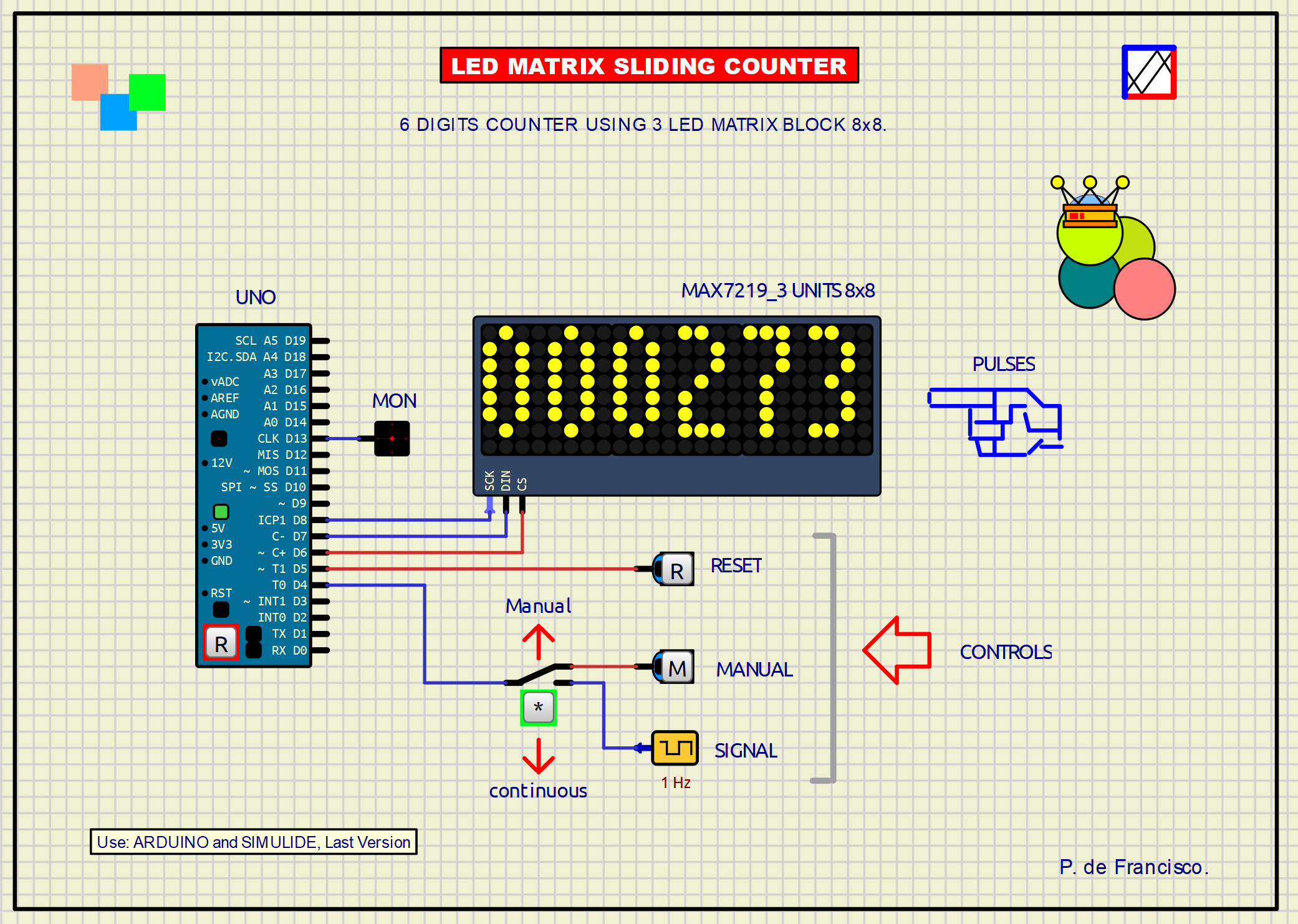
This example is a 6-digit counter with a scroll-up effect. The display is made up of three 8x8 pixel LED matrix blocks (MAX7219). The digits are made up of a 7x3 matrix with an extra column for separation, allowing two digits per LED block.
There are three controls for operation: A [MANUAL] button to manually advance the count, a switch to switch from manual to continuous advance using a 1Hz oscillator, a [RESET] button to reset the counter at all times and a LED monitor of pulses.
SCHEME:
The schematic is based on the Arduino UNO, Three MAX7219 LED matrix blocks, two pushbuttons and a switch. An LED has also been added as a monitor to show the arrival of pulses to the counter.
PROGRAM:
The external library used is: U8g2lib.h. The program is sufficiently commented, perhaps highlighting the use of the itoa command to convert numbers to characters.
// LED MATRIX COUNTER, 6 DIGITS 7X3. DEFRAN 24. #include <U8g2lib.h> U8G2_MAX7219_32X8_F_4W_SW_SPI u8g2(U8G2_R0,8,7,6,U8X8_PIN_NONE,U8X8_PIN_NONE); // clock, data, cs, DC, RESET byte digits[6]={0,0,0,0,0,0}; // DIGITS 7X3 MATRIX byte offsetPerc[6]={0,0,0,0,0,0}; // OFFSET MATRIX char Char[2]; // STYLE char CharNext[2]; // STORING STYLE float Offset; // OFFSET CHAR int Selv=1; int pre=1; int Sel=4; int Rese=5; int Mon=13; void setup(void) { u8g2.begin(); u8g2.setContrast(15*16); // LED BRIGHT u8g2.setFont(u8g2_font_minuteconsole_tr); // FONT FOR 7x3 pinMode(Sel, INPUT_PULLUP); // SELECTOR pinMode(Rese, INPUT_PULLUP); // RESET pinMode(Mon, OUTPUT); // MONITOR LED } void loop(void) { if (digitalRead(Rese)==LOW) {res(); u8g2.clearBuffer(); u8g2.sendBuffer();} // RESET Selv=digitalRead(Sel); // MANUAL ACTIVE: LOW if(Selv!=pre) // TOGGLE SIGNAL { if(Selv==1) { if (offsetPerc[5]==0) offsetPerc[5]=2; // LAST DIGIT ANIMATE AND INCREMENT digitalWrite(Mon,HIGH); // MON HIHG delay(60); // TIME FOR MON LED digitalWrite(Mon,LOW); // MON LOW } } pre=Selv; u8g2.clearBuffer(); // MEMORY CLEAR for (int i=5; i>=0; i--) { if (offsetPerc[i]>0) // FROM LAST DIGIT TO THE FIRST ANIMATION { offsetPerc[i]=offsetPerc[i]+10; // INCREMENT OFFSET PERCENTAGE if ((digits[i]==9) && (offsetPerc[i-1]==0) && (offsetPerc[i]>20)) { offsetPerc[i-1]=2; // FROM 9 TO 0, INCREASE LEFT DIGIT } if (offsetPerc[i] >= 100) // NEXT DIGIT IF ANIMATE DONE { offsetPerc[i]=0; // STOP ANIMATION digits[i]=digits[i]+1; // INCREASE if (digits[i]==10) {digits[i]=0;} // FROM 10 TO 0 } } Offset=round((1-((cos(offsetPerc[i]/100.0*3.141592654)/2.0)+0.5))*8.0); itoa(digits[i], Char,10); // NUMBER TO STYLE itoa((digits[i]+1) % 10, CharNext,10); // NEXT NUMBER TO STYLE u8g2.drawStr(i*4, 7-Offset, Char); // DARW CHARACTER u8g2.drawStr(i*4, 7-Offset+8, CharNext); // DRAW NEXT CHAR delay(10); // SLIDING TIME } u8g2.sendBuffer(); // MEMORY TO DISPLAY } void res() // RESET SUBRUTINE { for (int i=5; i>=0; i--) digits[i]=0; } // Wokw. insp.SUBCIRCUITS:This example integrates several subcircuits located in the "data" folder into the ZIP attached. This folder must always be next to the "sim1" scheme so that it can be executed. A subcircuit is a “custom” circuit that accumulates a set of Simulide base components (primitive function) to obtain a new or an adapted function. These subcircuits are treated by Simulide as another component of its own structure. User can create his own subcircuits or use the ones published here in your own designs once the procedure is known, explained in detail in the Simulide tutorials: https://simulide.com/p/subcircuits/More examples for Simulide are here: https://simulide.forumotion.com/f12-projects-made-in-simulide* Communication with the author: Simulide/User/Messages/DefranP. de Francisco.

367_LED_MATRIX SLIDING COUNTER. (Simulide 1.1.1973 or Higher).
This example is a 6-digit counter with a scroll-up effect. The display is made up of three 8x8 pixel LED matrix blocks (MAX7219). The digits are made up of a 7x3 matrix with an extra column for separation, allowing two digits per LED block.
There are three controls for operation: A [MANUAL] button to manually advance the count, a switch to switch from manual to continuous advance using a 1Hz oscillator, a [RESET] button to reset the counter at all times and a LED monitor of pulses.
SCHEME:
PROGRAM:
The external library used is: U8g2lib.h. The program is sufficiently commented, perhaps highlighting the use of the itoa command to convert numbers to characters.
// LED MATRIX COUNTER, 6 DIGITS 7X3. DEFRAN 24.

#include <U8g2lib.h>
U8G2_MAX7219_32X8_F_4W_SW_SPI u8g2(U8G2_R0,8,7,6,U8X8_PIN_NONE,U8X8_PIN_NONE); // clock, data, cs, DC, RESET
byte digits[6]={0,0,0,0,0,0};      // DIGITS 7X3 MATRIX
byte offsetPerc[6]={0,0,0,0,0,0};  // OFFSET MATRIX
char Char[2];                      // STYLE
char CharNext[2];                  // STORING STYLE
float Offset;                      // OFFSET CHAR
int Selv=1;
int pre=1;
int Sel=4;
int Rese=5;
int Mon=13;

void setup(void)
{
  u8g2.begin();
  u8g2.setContrast(15*16);                    // LED BRIGHT
  u8g2.setFont(u8g2_font_minuteconsole_tr);	  // FONT FOR 7x3
  pinMode(Sel, INPUT_PULLUP);                 // SELECTOR
  pinMode(Rese, INPUT_PULLUP);                // RESET
  pinMode(Mon, OUTPUT);                       // MONITOR LED
}

void loop(void)
{
  if (digitalRead(Rese)==LOW) {res(); u8g2.clearBuffer(); u8g2.sendBuffer();}  // RESET
  Selv=digitalRead(Sel);                     // MANUAL ACTIVE: LOW
  if(Selv!=pre)                              // TOGGLE SIGNAL
  {
    if(Selv==1)
    {
      if (offsetPerc[5]==0) offsetPerc[5]=2;  // LAST DIGIT ANIMATE AND INCREMENT
      digitalWrite(Mon,HIGH);                 // MON HIHG
      delay(60);                              // TIME FOR MON LED
      digitalWrite(Mon,LOW);                  // MON LOW
    }
  }
  pre=Selv;
  u8g2.clearBuffer();	                      // MEMORY CLEAR
  for (int i=5; i>=0; i--)
  {
    if (offsetPerc[i]>0)                      // FROM LAST DIGIT TO THE FIRST ANIMATION
    {
      offsetPerc[i]=offsetPerc[i]+10;         // INCREMENT OFFSET PERCENTAGE
      if ((digits[i]==9) && (offsetPerc[i-1]==0) && (offsetPerc[i]>20))
      {
        offsetPerc[i-1]=2;                    // FROM 9 TO 0, INCREASE LEFT DIGIT
      }
      if (offsetPerc[i] >= 100)               // NEXT DIGIT IF ANIMATE DONE
      {
        offsetPerc[i]=0;                      // STOP ANIMATION
        digits[i]=digits[i]+1;                // INCREASE
        if (digits[i]==10) {digits[i]=0;}     // FROM 10 TO 0
      }
    }
    Offset=round((1-((cos(offsetPerc[i]/100.0*3.141592654)/2.0)+0.5))*8.0);
    itoa(digits[i], Char,10);                  // NUMBER TO STYLE
    itoa((digits[i]+1) % 10, CharNext,10);     // NEXT NUMBER TO STYLE
    u8g2.drawStr(i*4, 7-Offset, Char);         // DARW CHARACTER
    u8g2.drawStr(i*4, 7-Offset+8, CharNext);   // DRAW NEXT CHAR
    delay(10);                                 // SLIDING TIME
  }
  u8g2.sendBuffer();  // MEMORY TO DISPLAY
}

void res()            // RESET SUBRUTINE
{
  for (int i=5; i>=0; i--)
  digits[i]=0;
} // Wokw. insp.
