
364__TEMPERATURE CONTROL WITH THE IC LM35
Quote from Defran on March 29, 2024, 10:48 am
364_TEMPERATURE CONTROL WITH THE IC LM35. (Simulide R2259 or Higher).
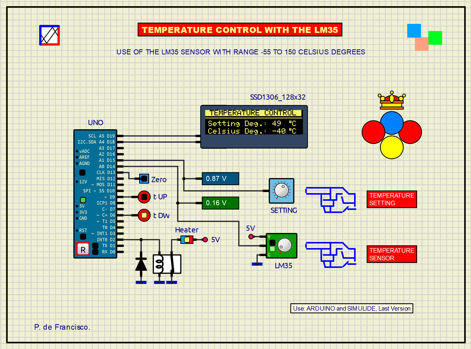
The LM35 is an integrated circuit that acts as a precision temperature sensor capable of delivering a linear signal for a temperature between -55 and 150 ºC. In our circuit we use this sensor as a measuring element and an adjustable reference value to control a heater. Both values are shown on the OLED display along with an active label that shows the voltage of each one. The t ºC, Zero LED lights up when the temperature is zero degrees. The t-UP and t-DW LEDs show when the temperature is above or below the set reference value respectively. A relay has been connected to output D2 to activate the heater. When the temperature of the medium to be controlled is below the reference value, the heater is switched on and turned off when it has exceeded it. On this occasion, a hysteresis band has not been established because the thermal inertia itself acts with that effect.
SCHEME:
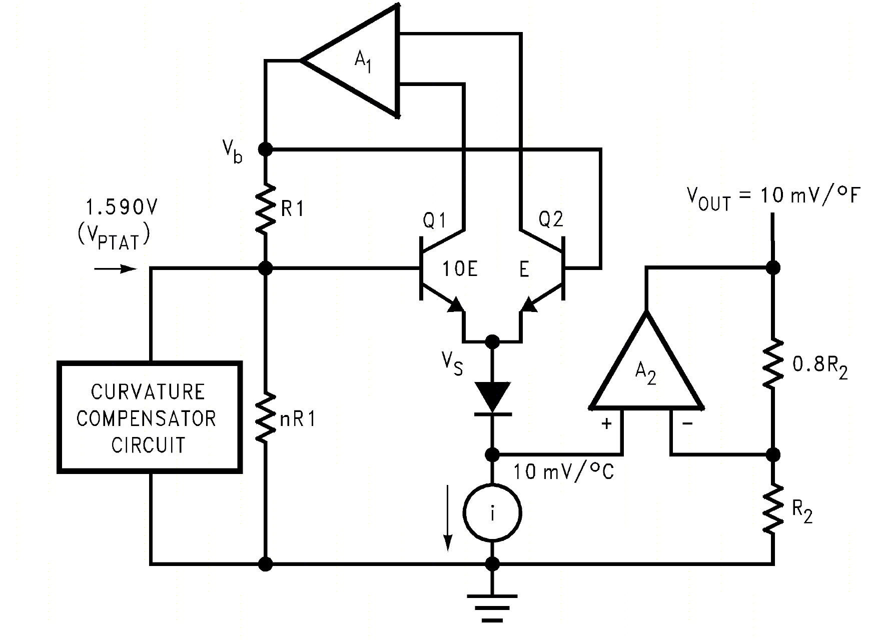
In our scheme, the LM35 is a subcircuit powered at 5V that manually simulates the temperature variation, in it two LEDs show when the temperature is above or below zero degrees. The signal from this sensor is entered through A0 of the controller, the reference signal is entered through A1. Both devices deliver a voltage between 0 and 1.5V for the entire range. The respective voltages are shown on each active label. The relay that connects the heater is connected to output D2. The OLED display is connected via I2C to the specific pins of the controller. The following figure shows the functional diagram of the LM35:
To know more obout the IC LM35: https://www.ti.com/lit/ds/symlink/lm35.pdf
PROGRAM:
The libraries included in the Arduino IDE are used: Wire.h, Adafruit_GFX.h and Adafruit_SSD1306.h. To measure the temperature, a conversion device from 0 to 308 steps has been used based on mapping taking into account the positive and negative ranges. Decimals have not been used due to the wide operating range, from -55 to 150 ºC.
// TEMPERATURE CONTROL WITH THE SENSOR LM35. DEFRAN24

#include <Wire.h>
#include <Adafruit_GFX.h>
#include <Adafruit_SSD1306.h>
Adafruit_SSD1306 display(128,32,&Wire,20);
int up=9;
int dw=6;
int rel=2;
int mon=13;
int t;
int s;

void setup()
{
  pinMode(mon, OUTPUT);
  pinMode(up, OUTPUT);
  pinMode(dw, OUTPUT);
  pinMode(rel, OUTPUT);
  display.begin(SSD1306_SWITCHCAPVCC, 0x3C); // Address 0x3C (60 DECIMAL)
}

void loop()
{
  s=analogRead(A1);  // TEMPERATURE SETTING INPUT
  t=analogRead(A0);  // TEMPERATURE SENSOR INPUT
  Serial.println(t);
  if (t>111 & t<115) digitalWrite(mon,HIGH); // LED Zero
  else digitalWrite(mon,LOW);
  display.clearDisplay();
  display.setTextSize(1);
  display.setTextColor(BLACK, WHITE);       // WHITE BACKGROUND
  display.setCursor(0,0);
  display.print(" TEMPERATURE CONTROL ");
  display.drawLine(0,10,126,10,WHITE);      // LINE X,Y,WIDTH, Y FIN
  display.setTextColor(WHITE);
  display.setCursor(4,14);
  display.print("Setting Deg.: ");
  if (s>=109) s=map(s,113,306,  0,150);
  else s=map(s,0,113, -55,0);               // Setting
  display.print(s);
  display.drawRect(110,14,3,3, WHITE);      // Degree symbol
  display.setCursor(114,14);
  display.print("C");
  display.setCursor(4,24);
  display.print("Celsius Deg.: ");
  if (t>=109) t=map(t,113,306, 0,150);     // Temperature
  else t=map(t,0,113,-55,0);
  display.print(t);
  display.drawRect(110,24,3,3, WHITE);     // Degree symbol
  display.setCursor(114,24);
  display.print("C");
  display.display();
  if (t>s) {digitalWrite(up,HIGH); digitalWrite (rel, LOW);} // HEATER
  else digitalWrite(up,LOW);
  if (t<s) {digitalWrite(dw,HIGH); digitalWrite (rel, HIGH);} // HEATER
  else digitalWrite(dw,LOW);
  delay(100);
}
SUBCIRCUITS:
This example integrates several subcircuits located in the "data" folder into the ZIP attached. This folder must always be next to the "sim1" scheme so that it can be executed. A subcircuit is a “custom” circuit that accumulates a set of Simulide base components (primitive function) to obtain a new or an adapted function. These subcircuits are treated by Simulide as another component of its own structure. User can create his own subcircuits or use the ones published here in your own designs once the procedure is known, explained in detail in the Simulide tutorials: https://simulide.com/p/subcircuits/* Communication with the author: Simulide/User/Messages/DefranP. de Francisco.
364_TEMPERATURE CONTROL WITH THE IC LM35. (Simulide R2259 or Higher).
The LM35 is an integrated circuit that acts as a precision temperature sensor capable of delivering a linear signal for a temperature between -55 and 150 ºC. In our circuit we use this sensor as a measuring element and an adjustable reference value to control a heater. Both values are shown on the OLED display along with an active label that shows the voltage of each one. The t ºC, Zero LED lights up when the temperature is zero degrees. The t-UP and t-DW LEDs show when the temperature is above or below the set reference value respectively. A relay has been connected to output D2 to activate the heater. When the temperature of the medium to be controlled is below the reference value, the heater is switched on and turned off when it has exceeded it. On this occasion, a hysteresis band has not been established because the thermal inertia itself acts with that effect.
SCHEME:
In our scheme, the LM35 is a subcircuit powered at 5V that manually simulates the temperature variation, in it two LEDs show when the temperature is above or below zero degrees. The signal from this sensor is entered through A0 of the controller, the reference signal is entered through A1. Both devices deliver a voltage between 0 and 1.5V for the entire range. The respective voltages are shown on each active label. The relay that connects the heater is connected to output D2. The OLED display is connected via I2C to the specific pins of the controller. The following figure shows the functional diagram of the LM35:
To know more obout the IC LM35: https://www.ti.com/lit/ds/symlink/lm35.pdf
PROGRAM:
The libraries included in the Arduino IDE are used: Wire.h, Adafruit_GFX.h and Adafruit_SSD1306.h. To measure the temperature, a conversion device from 0 to 308 steps has been used based on mapping taking into account the positive and negative ranges. Decimals have not been used due to the wide operating range, from -55 to 150 ºC.
// TEMPERATURE CONTROL WITH THE SENSOR LM35. DEFRAN24

#include <Wire.h>
#include <Adafruit_GFX.h>
#include <Adafruit_SSD1306.h>
Adafruit_SSD1306 display(128,32,&Wire,20);
int up=9;
int dw=6;
int rel=2;
int mon=13;
int t;
int s;

void setup()
{
  pinMode(mon, OUTPUT);
  pinMode(up, OUTPUT);
  pinMode(dw, OUTPUT);
  pinMode(rel, OUTPUT);
  display.begin(SSD1306_SWITCHCAPVCC, 0x3C); // Address 0x3C (60 DECIMAL)
}

void loop()
{
  s=analogRead(A1);  // TEMPERATURE SETTING INPUT
  t=analogRead(A0);  // TEMPERATURE SENSOR INPUT
  Serial.println(t);
  if (t>111 & t<115) digitalWrite(mon,HIGH); // LED Zero
  else digitalWrite(mon,LOW);
  display.clearDisplay();
  display.setTextSize(1);
  display.setTextColor(BLACK, WHITE);       // WHITE BACKGROUND
  display.setCursor(0,0);
  display.print(" TEMPERATURE CONTROL ");
  display.drawLine(0,10,126,10,WHITE);      // LINE X,Y,WIDTH, Y FIN
  display.setTextColor(WHITE);
  display.setCursor(4,14);
  display.print("Setting Deg.: ");
  if (s>=109) s=map(s,113,306,  0,150);
  else s=map(s,0,113, -55,0);               // Setting
  display.print(s);
  display.drawRect(110,14,3,3, WHITE);      // Degree symbol
  display.setCursor(114,14);
  display.print("C");
  display.setCursor(4,24);
  display.print("Celsius Deg.: ");
  if (t>=109) t=map(t,113,306, 0,150);     // Temperature
  else t=map(t,0,113,-55,0);
  display.print(t);
  display.drawRect(110,24,3,3, WHITE);     // Degree symbol
  display.setCursor(114,24);
  display.print("C");
  display.display();
  if (t>s) {digitalWrite(up,HIGH); digitalWrite (rel, LOW);} // HEATER
  else digitalWrite(up,LOW);
  if (t<s) {digitalWrite(dw,HIGH); digitalWrite (rel, HIGH);} // HEATER
  else digitalWrite(dw,LOW);
  delay(100);
}
SUBCIRCUITS: