
Technical detail on the wire drawing and routing
Quote from Theklo on April 11, 2026, 6:13 amHello, I'm new here. I'm coming just to ask about how this simulator handles connections between devices.
I've been trying to make my own circuit simulator (using the Godot engine) for digital circuits. So, more like a toy version of Logisim.
Both Logisim and SimulIDE seem to handle wires in the same way and I'm trying to replicate that method.I don't mean how components or sockets signal each other, that part I've solved, but in the UI, when the user draws or edits a line from one socket to the other or on the canvas. How are these wire stored in a data structure and rendered, how can they tell if the user clicked on them, how are they edited?
I've tried several approaches, but always hit some problem, either on how to branch wires, or route wires for a more complicated path.
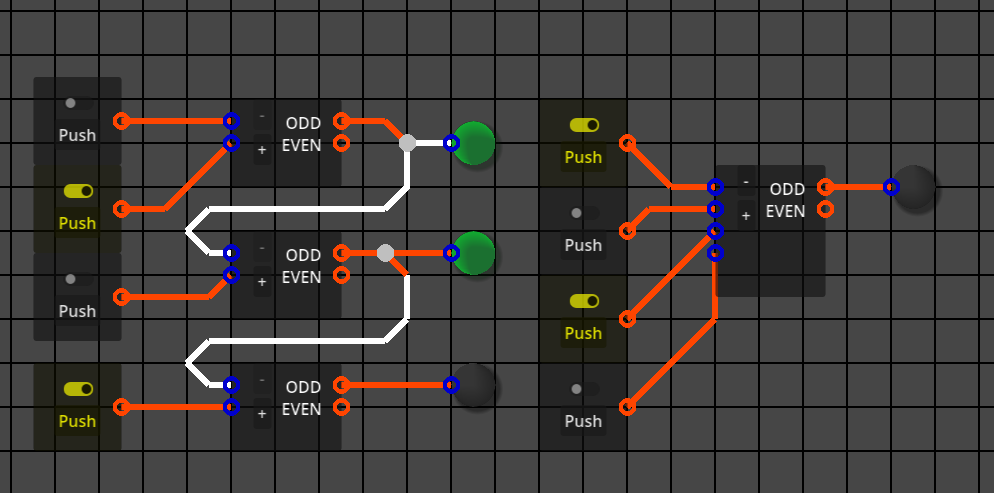
Here's a picture of a prototype of my simulator where the wires are represented as point-to-point lines that can't be edited.
Hello, I'm new here. I'm coming just to ask about how this simulator handles connections between devices.
I've been trying to make my own circuit simulator (using the Godot engine) for digital circuits. So, more like a toy version of Logisim.
Both Logisim and SimulIDE seem to handle wires in the same way and I'm trying to replicate that method.
I don't mean how components or sockets signal each other, that part I've solved, but in the UI, when the user draws or edits a line from one socket to the other or on the canvas. How are these wire stored in a data structure and rendered, how can they tell if the user clicked on them, how are they edited?
I've tried several approaches, but always hit some problem, either on how to branch wires, or route wires for a more complicated path.
Here's a picture of a prototype of my simulator where the wires are represented as point-to-point lines that can't be edited.
Quote from arcachofo on April 11, 2026, 1:21 pmImplementing wires is the most complicated thing in the UI, way more complicated that it seems at first glance.
This is not something you can not do in one weekend, or maybe you can, but it took me hundreds of hours of work just to get the basics working, then years to fix all the edge cases.
You will hit many problems, you just solve one after another after another...A wire can be represented as a list of points, each point is the 2º point of a line and the 1º point of the next line (except first and last).
When you move a component or a line the list must be updated to do what you want.
Technical details depend on the framework you use.
Implementing wires is the most complicated thing in the UI, way more complicated that it seems at first glance.
This is not something you can not do in one weekend, or maybe you can, but it took me hundreds of hours of work just to get the basics working, then years to fix all the edge cases.
You will hit many problems, you just solve one after another after another...
A wire can be represented as a list of points, each point is the 2º point of a line and the 1º point of the next line (except first and last).
When you move a component or a line the list must be updated to do what you want.
Technical details depend on the framework you use.
Quote from Theklo on April 12, 2026, 1:02 pmSo, you could say that wires are doubly connected edge lists? I know someone who is making a 3D modelling program around that concept.
So, you could say that wires are doubly connected edge lists? I know someone who is making a 3D modelling program around that concept.
Quote from arcachofo on April 13, 2026, 11:40 pmQuote from Theklo on April 12, 2026, 1:02 pmSo, you could say that wires are doubly connected edge lists? I know someone who is making a 3D modelling program around that concept.
In simulide wires are just simple lists of points.
From those points you draw lines.But this could be done in many ways I guess.
At the end is just a bunch of lines that somehow are linked to the previous one and the next one.
Quote from Theklo on April 12, 2026, 1:02 pmSo, you could say that wires are doubly connected edge lists? I know someone who is making a 3D modelling program around that concept.
In simulide wires are just simple lists of points.
From those points you draw lines.
But this could be done in many ways I guess.
At the end is just a bunch of lines that somehow are linked to the previous one and the next one.
Quote from Theklo on April 28, 2026, 2:21 pmI've been chipping away at this problem for a while and thought it might a good idea to share, maybe get some feedback.
My simulator already made use of a space partitioning system, specifically spatial hashes. So there's a dictionary of a partition coordinate associated to an array of objects within. The coordinate acts like the key to the dictionary and is just the position of some object snapped/rounded to the some arbitrary value (the size of the partitions).
I have a partition dictionary for just vertices of a wire. The coordinates were a line begins, ends or bends. The vertices are a simple class, holding a position and a list of other vertices they connect to. They also include a function that returns which of the connected vertices represent an horizontal or vertical segment of wire.
I also made a "get_wire_segments()" which returns an array of pairs of vertices representing a valid segment. It only returns segments inside an area represented by a rectangle (Rect2):
func get_wire_segments(canvas_rect:Rect2) -> Array:
	var segm : Array
	var checked : Dictionary[FlowchartGraph.Vertex, Array]
	for v in parti.wire.find_objects(canvas_rect):
		checked[v] = []
		for c in v.conn:
			if not c in checked or not v in checked[c]:
				checked[v].append(c)
				segm.append([v, c])
	return segm
As you can see, my functions to find segments make sure there aren't redundancies, like, if there's a [v1, v4], it won't include [v4, v1].
When drawing a wire, it uses this function and draws lines between the positions of the returned segments. But be aware that segments are never stored anywhere as their own entity.By constraining wire segments to only be vertical or horizontal, we can tell which ones they are by checking the position of every two vertices (each segment) for whether they have the same X value (they are vertical) or the same Y value (they are horizontal). Eventually I'd like to implement a way to also include 45deg diagonals, but let's keep it simple for now.
The way to detect if segments were clicked is by:
1 - Getting the vertices of the partition where the mouse is.
2 - Getting unique segments from those vertices, stored on either a "horizontal" or "vertical" list separately.
3 - If horizontal, then see if the mouse X coordinate is within range between the coordinate X of vertex pairs.
4 - If vertical, see if mouse Y falls between Y coordinates of the vertex pair.
5 - Put matches in a list and select one of them. Which one depends on your preference.The canvas drawing function then uses this list to render the given segments highlighted.
When creating a new wires, it will start from a socket. I haven't implemented a mechanism to associate vertices to sockets yet, but I imagine at some point, vertices would be grouped by another class that represents a single network, then that class is what keeps track of which vertices are associated to which socket.
There is function that's called when a wire is initiated from a socket, a different one when it is initiated at the click on a segment. Then another function is called if the wire is ended at a socket, and a function if a wire is ended somewhere in the canvas. When a wire is initiated, there's a sort of temporary wire variable. The canvas drawing function uses this to indicate the wiring operation. It will find two coordinates (apart from the starting one) that produce orthogonal segments from the start point to the mouse position.
When the wire is ended, submitting the temporary wire, it will create new vertex instances for the coordinates found during drawing. I haven't progress much further in the project from, this, but the big next thing would be to flag that a wire network was changed. This will call an optimization function that finds superfluous vertices (like when there are two horizontals in a row without branch) to remove them, or add vertices if the line between two of them doesn't produce an orthogonal path (effectively breaking one segment into two). When this kind of thing is done, it is necessary to re-assign connections of affected vertices. This sounds like an headache.
If you are checking every pair of vertices, seeing their neighbors, checking if there's redundancy, you might find a few of the redundant ones, but not all of them. For example, if there's a single horizontal like with 5 vertices. It would be necessary to repeat this operation until no more optimizations can be done and this is not great programming practice. I need a proper way to detect if there are, say "recursive" redundancies and solve them all in one iteration.
I've considered approaching this as a pathfinding problem and use something like A-Star to map the vertices make a list of those with the same score or whatever. I didn't think this thoroughly yet. It might also be a way to tell to which network a vertex belongs. For example three vertices initially connected together would belong in the same network, until you delete one in the middle, then the other two now belong to isolated networks.
I've been chipping away at this problem for a while and thought it might a good idea to share, maybe get some feedback.
My simulator already made use of a space partitioning system, specifically spatial hashes. So there's a dictionary of a partition coordinate associated to an array of objects within. The coordinate acts like the key to the dictionary and is just the position of some object snapped/rounded to the some arbitrary value (the size of the partitions).
I have a partition dictionary for just vertices of a wire. The coordinates were a line begins, ends or bends. The vertices are a simple class, holding a position and a list of other vertices they connect to. They also include a function that returns which of the connected vertices represent an horizontal or vertical segment of wire.
I also made a "get_wire_segments()" which returns an array of pairs of vertices representing a valid segment. It only returns segments inside an area represented by a rectangle (Rect2):
func get_wire_segments(canvas_rect:Rect2) -> Array:
	var segm : Array
	var checked : Dictionary[FlowchartGraph.Vertex, Array]
	for v in parti.wire.find_objects(canvas_rect):
		checked[v] = []
		for c in v.conn:
			if not c in checked or not v in checked[c]:
				checked[v].append(c)
				segm.append([v, c])
	return segm
As you can see, my functions to find segments make sure there aren't redundancies, like, if there's a [v1, v4], it won't include [v4, v1].
When drawing a wire, it uses this function and draws lines between the positions of the returned segments. But be aware that segments are never stored anywhere as their own entity.
By constraining wire segments to only be vertical or horizontal, we can tell which ones they are by checking the position of every two vertices (each segment) for whether they have the same X value (they are vertical) or the same Y value (they are horizontal). Eventually I'd like to implement a way to also include 45deg diagonals, but let's keep it simple for now.
The way to detect if segments were clicked is by:
1 - Getting the vertices of the partition where the mouse is.
2 - Getting unique segments from those vertices, stored on either a "horizontal" or "vertical" list separately.
3 - If horizontal, then see if the mouse X coordinate is within range between the coordinate X of vertex pairs.
4 - If vertical, see if mouse Y falls between Y coordinates of the vertex pair.
5 - Put matches in a list and select one of them. Which one depends on your preference.
The canvas drawing function then uses this list to render the given segments highlighted.
When creating a new wires, it will start from a socket. I haven't implemented a mechanism to associate vertices to sockets yet, but I imagine at some point, vertices would be grouped by another class that represents a single network, then that class is what keeps track of which vertices are associated to which socket.
There is function that's called when a wire is initiated from a socket, a different one when it is initiated at the click on a segment. Then another function is called if the wire is ended at a socket, and a function if a wire is ended somewhere in the canvas. When a wire is initiated, there's a sort of temporary wire variable. The canvas drawing function uses this to indicate the wiring operation. It will find two coordinates (apart from the starting one) that produce orthogonal segments from the start point to the mouse position.
When the wire is ended, submitting the temporary wire, it will create new vertex instances for the coordinates found during drawing. I haven't progress much further in the project from, this, but the big next thing would be to flag that a wire network was changed. This will call an optimization function that finds superfluous vertices (like when there are two horizontals in a row without branch) to remove them, or add vertices if the line between two of them doesn't produce an orthogonal path (effectively breaking one segment into two). When this kind of thing is done, it is necessary to re-assign connections of affected vertices. This sounds like an headache.
If you are checking every pair of vertices, seeing their neighbors, checking if there's redundancy, you might find a few of the redundant ones, but not all of them. For example, if there's a single horizontal like with 5 vertices. It would be necessary to repeat this operation until no more optimizations can be done and this is not great programming practice. I need a proper way to detect if there are, say "recursive" redundancies and solve them all in one iteration.
I've considered approaching this as a pathfinding problem and use something like A-Star to map the vertices make a list of those with the same score or whatever. I didn't think this thoroughly yet. It might also be a way to tell to which network a vertex belongs. For example three vertices initially connected together would belong in the same network, until you delete one in the middle, then the other two now belong to isolated networks.
Quote from arcachofo on April 30, 2026, 9:04 amThe framework used conditions a lot how to implement functionality.
Simulide uses Qt, so lines can receive mouse events.
Then wires are built based on this: a wire is just a list of lines defined by a list of points.One thing that could be different from your approach (but I'm not sure) is that a wire has just an start and an end, no branches.
Branches are different wires.Starting and ending a wire, then "cleaning" is similar.
I don't understand why you want to know which network a vertex belong.
At the end all you need is to group pins, terminals or sockets into electric nodes.
At the beginning I did keep track of this while drawing, but this is a headache. Now it is done before simulation start.
The framework used conditions a lot how to implement functionality.
Simulide uses Qt, so lines can receive mouse events.
Then wires are built based on this: a wire is just a list of lines defined by a list of points.
One thing that could be different from your approach (but I'm not sure) is that a wire has just an start and an end, no branches.
Branches are different wires.
Starting and ending a wire, then "cleaning" is similar.
I don't understand why you want to know which network a vertex belong.
At the end all you need is to group pins, terminals or sockets into electric nodes.
At the beginning I did keep track of this while drawing, but this is a headache. Now it is done before simulation start.