
Technical detail on the wire drawing and routing
Quote from Theklo on April 11, 2026, 6:13 amHello, I'm new here. I'm coming just to ask about how this simulator handles connections between devices.
I've been trying to make my own circuit simulator (using the Godot engine) for digital circuits. So, more like a toy version of Logisim.
Both Logisim and SimulIDE seem to handle wires in the same way and I'm trying to replicate that method.I don't mean how components or sockets signal each other, that part I've solved, but in the UI, when the user draws or edits a line from one socket to the other or on the canvas. How are these wire stored in a data structure and rendered, how can they tell if the user clicked on them, how are they edited?
I've tried several approaches, but always hit some problem, either on how to branch wires, or route wires for a more complicated path.
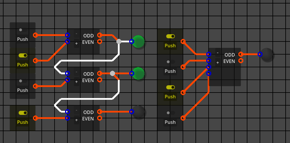
Here's a picture of a prototype of my simulator where the wires are represented as point-to-point lines that can't be edited.
Hello, I'm new here. I'm coming just to ask about how this simulator handles connections between devices.
I've been trying to make my own circuit simulator (using the Godot engine) for digital circuits. So, more like a toy version of Logisim.
Both Logisim and SimulIDE seem to handle wires in the same way and I'm trying to replicate that method.
I don't mean how components or sockets signal each other, that part I've solved, but in the UI, when the user draws or edits a line from one socket to the other or on the canvas. How are these wire stored in a data structure and rendered, how can they tell if the user clicked on them, how are they edited?
I've tried several approaches, but always hit some problem, either on how to branch wires, or route wires for a more complicated path.
Here's a picture of a prototype of my simulator where the wires are represented as point-to-point lines that can't be edited.
Quote from arcachofo on April 11, 2026, 1:21 pmImplementing wires is the most complicated thing in the UI, way more complicated that it seems at first glance.
This is not something you can not do in one weekend, or maybe you can, but it took me hundreds of hours of work just to get the basics working, then years to fix all the edge cases.
You will hit many problems, you just solve one after another after another...A wire can be represented as a list of points, each point is the 2º point of a line and the 1º point of the next line (except first and last).
When you move a component or a line the list must be updated to do what you want.
Technical details depend on the framework you use.
Implementing wires is the most complicated thing in the UI, way more complicated that it seems at first glance.
This is not something you can not do in one weekend, or maybe you can, but it took me hundreds of hours of work just to get the basics working, then years to fix all the edge cases.
You will hit many problems, you just solve one after another after another...
A wire can be represented as a list of points, each point is the 2º point of a line and the 1º point of the next line (except first and last).
When you move a component or a line the list must be updated to do what you want.
Technical details depend on the framework you use.