
ssd1306
Quote from arS on January 17, 2026, 8:12 amHi,
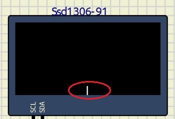
I hope someone can point me to the right direction of the issue that I'm having with the ssd1306 display. I printed one vertical line intended to be displayed in the PAGE0 and the 5th column.
For some reason, the output is always at the bottom PAGE and in the middle of the 128 columns no matter how I changed the setting.
I have attached the .s file from MAP X IDE, the sim1 file and the .hex file.
Press '1' for setting, press '2' send the vertical line to ssd1306 for display.
Thanks & regards
Albert
Hi,
I hope someone can point me to the right direction of the issue that I'm having with the ssd1306 display. I printed one vertical line intended to be displayed in the PAGE0 and the 5th column.
For some reason, the output is always at the bottom PAGE and in the middle of the 128 columns no matter how I changed the setting.
I have attached the .s file from MAP X IDE, the sim1 file and the .hex file.
Press '1' for setting, press '2' send the vertical line to ssd1306 for display.
Thanks & regards
Albert
Uploaded files:
Quote from arcachofo on January 17, 2026, 2:05 pmHi there.
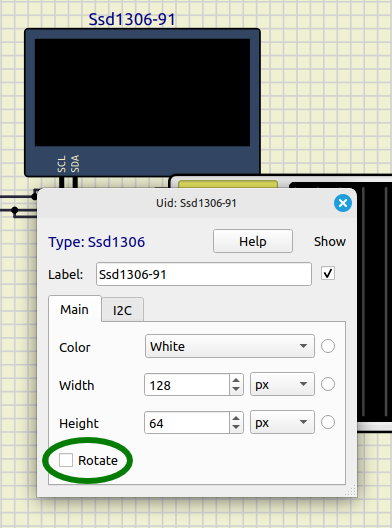
To solve output at the bottom uncheck "Rotate" in properties:
And it is in the middle because that is the X address that SSD1306 is receiving.
Maybe there is some issue in the code, because X address received is a bit weird.
This are the commands and parameters received whem button 1 is pressed:Command 0xFF
Command 0x0
Command 0x81
Parameter 64
Command 0xFF
Command 0x80
Command 0xA6
Command 0x2E
Command 0x0
Command 0x26
Parameter 192
Parameter 0
Parameter 0
Parameter 0
Parameter 7
Parameter 0
Command 0xFF
Command 0x0
Command 0x20
Parameter 64
Command 0x0
Command 0x0
Command 0x22
Parameter 192 ---- StartY
Parameter 0 ---- EndY
Command 0x7
Command 0x0
Command 0x21
Parameter 192 ---- StartX
Parameter 5 ---- EndX
Command 0x7A
Command 0x0
Command 0x40
Command 0x0
Command 0xA0
Command 0x0
Command 0xA8
Parameter 64
Command 0x3F
Command 0x0
Command 0xC0
Command 0x0
Command 0xD3
Parameter 64
Command 0x0
Command 0x0
Command 0xDA
Parameter 64
Command 0x12
Command 0x0
Command 0xD5
Parameter 64
Command 0x80
Command 0x0
Command 0xD9
Parameter 64
Command 0x22
Parameter 0 ---- StartY
Parameter 219 ---- EndY
Command 0x40
Command 0x20
Parameter 0
Command 0x8D
Parameter 64
Command 0x14
Command 0x0
Command 0xA4
Command 0x0
Command 0xAF
Hi there.
To solve output at the bottom uncheck "Rotate" in properties:
And it is in the middle because that is the X address that SSD1306 is receiving.
Maybe there is some issue in the code, because X address received is a bit weird.
This are the commands and parameters received whem button 1 is pressed:
Command 0xFF
Command 0x0
Command 0x81
Parameter 64
Command 0xFF
Command 0x80
Command 0xA6
Command 0x2E
Command 0x0
Command 0x26
Parameter 192
Parameter 0
Parameter 0
Parameter 0
Parameter 7
Parameter 0
Command 0xFF
Command 0x0
Command 0x20
Parameter 64
Command 0x0
Command 0x0
Command 0x22
Parameter 192 ---- StartY
Parameter 0 ---- EndY
Command 0x7
Command 0x0
Command 0x21
Parameter 192 ---- StartX
Parameter 5 ---- EndX
Command 0x7A
Command 0x0
Command 0x40
Command 0x0
Command 0xA0
Command 0x0
Command 0xA8
Parameter 64
Command 0x3F
Command 0x0
Command 0xC0
Command 0x0
Command 0xD3
Parameter 64
Command 0x0
Command 0x0
Command 0xDA
Parameter 64
Command 0x12
Command 0x0
Command 0xD5
Parameter 64
Command 0x80
Command 0x0
Command 0xD9
Parameter 64
Command 0x22
Parameter 0 ---- StartY
Parameter 219 ---- EndY
Command 0x40
Command 0x20
Parameter 0
Command 0x8D
Parameter 64
Command 0x14
Command 0x0
Command 0xA4
Command 0x0
Command 0xAF
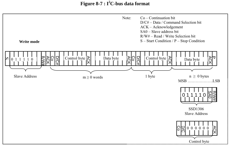
Quote from arcachofo on January 17, 2026, 8:09 pmI did some investigation about this and I think your code is doing what is shown in the datasheet.
In this figure it seems to suggest that you must send a control byte then a data byte:
But the reality is that it doesn't seem to work that way.
For example this is part of the initialization routine used in an Arduino library for SSD1306.
It uses a single control byte after sending the address:Start
Address
Control Byte 0
Command 0xAE
Command 0xD5
Parameter 128
Command 0xA8
StopStart
Address
Control Byte 0
Parameter 63
StopStart
Address
Control Byte 0
Command 0xD3
Parameter 0
Command 0x40
Command 0x8D
StopStart
Address
Control Byte 0
Parameter 20
StopAnd something similar to send data to SSD1306 memory (but bit D/C=1):
Start
Address
Control Byte 64 <------------------------------ bit D/C=1
Ssd1306::writeData 0 0 0
Ssd1306::writeData 1 0 0
...
...
Ssd1306::writeData 29 0 0
Ssd1306::writeData 30 0 0
StopIn theory you could send start, address, a single control byte = 0 followed by all the initialization commands and then stop.
I did some investigation about this and I think your code is doing what is shown in the datasheet.
In this figure it seems to suggest that you must send a control byte then a data byte:
But the reality is that it doesn't seem to work that way.
For example this is part of the initialization routine used in an Arduino library for SSD1306.
It uses a single control byte after sending the address:
Start
Address
Control Byte 0
Command 0xAE
Command 0xD5
Parameter 128
Command 0xA8
Stop
Start
Address
Control Byte 0
Parameter 63
Stop
Start
Address
Control Byte 0
Command 0xD3
Parameter 0
Command 0x40
Command 0x8D
Stop
Start
Address
Control Byte 0
Parameter 20
Stop
And something similar to send data to SSD1306 memory (but bit D/C=1):
Start
Address
Control Byte 64 <------------------------------ bit D/C=1
Ssd1306::writeData 0 0 0
Ssd1306::writeData 1 0 0
...
...
Ssd1306::writeData 29 0 0
Ssd1306::writeData 30 0 0
Stop
In theory you could send start, address, a single control byte = 0 followed by all the initialization commands and then stop.
Quote from arS on January 18, 2026, 10:56 amHi arcachofo,
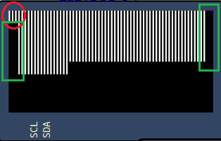
Thanks you very much of all these information. I uncheck the 'rotate' box and use a single cmd control byte (= 0x00). The vertical line did start at the 1st column in PAGE0. But my start column is set at the 5th column and last column is at 122nd column. Not sure why it starts at the 1st column? I then repeat alternate vertical lines to see if it gets to the next PAGE1, PAGE2, etc. I've noticed that it does end at 122 column instead of the 128 column. Also, PAGE1 and after do start at the 5th column except the PAGE0.
As for the examples from the Arduino control bytes, it only uses 0x00 for cmd and 0x40 for data regardless of number of cmd and data records to follow. I read from this article and somewhere else that there are 4 different control bytes. They're 0x00 for single cmd, 0x80 for multiple cmds, 0x40 for single data record and 0xC0 for multiple data records. It didn't look like this simulation recognize 0x80 or 0xC0 when I tried. Do I need to change it to 0x80 and 0xC0 when implementing to the actual hardware?
Best regards
Hi arcachofo,
Thanks you very much of all these information. I uncheck the 'rotate' box and use a single cmd control byte (= 0x00). The vertical line did start at the 1st column in PAGE0. But my start column is set at the 5th column and last column is at 122nd column. Not sure why it starts at the 1st column? I then repeat alternate vertical lines to see if it gets to the next PAGE1, PAGE2, etc. I've noticed that it does end at 122 column instead of the 128 column. Also, PAGE1 and after do start at the 5th column except the PAGE0.
As for the examples from the Arduino control bytes, it only uses 0x00 for cmd and 0x40 for data regardless of number of cmd and data records to follow. I read from this article and somewhere else that there are 4 different control bytes. They're 0x00 for single cmd, 0x80 for multiple cmds, 0x40 for single data record and 0xC0 for multiple data records. It didn't look like this simulation recognize 0x80 or 0xC0 when I tried. Do I need to change it to 0x80 and 0xC0 when implementing to the actual hardware?
Best regards
Quote from arcachofo on January 18, 2026, 2:25 pmThere is a lot of confussion about control byte, the information in the datasheet doesn't make much sense and the information in the internet is wrong in many cases.
I faced this problem when implementing SSD1306, so at the end I just made it work for the most used libraries even when I didn't actually understand how it works.
The problem comes from the bit 7: Co.
I did some more investigation and now it makes sense for me.
The article you mention and many others have it wrong, and to add confussion, the example code in that article uses 0x00 and 0x40 for multiple data, just the opposite of what he says in the explanations.
At the end, in the comments someone points at the error and later another user explains the correct interpretation:Co = 1 : there will be more control bytes in this transmission.
Co = 0 : no more control bytes for this transmission.With Co = 1 you can send data and commands in the same transmission, but you must send a control byte for each data/command.
After sending a control byte with Co = 0 the following bytes must be only data or only commands until the end of transmission.When I say "commands" I mean commands and command parameters.
Data refers to data to be saved to Display RAM.Everybody uses Co = 0 because it seems more convenient.
But I guess Co = 1 could be used like this for example:Start
Address
Control Byte 0x80 <---- Command, Co = 1, more control bytes will come
Command
Control Byte 0x80 <---- Command, Co = 1, more control bytes will come
Command
Parameter
Control Byte 0xC0 <---- Data, Co = 1, more control bytes will come
data
Control Byte 0x80 <---- Command, Co = 1, more control bytes will come
Command
Control Byte 0x40 <---- Data, Co = 0, no more control bytes, next bytes will be all data
data
data
data
data
data
data
data
data
data
data
data
data
StopStill not sure about the second command, it should be like this:
Control Byte 0x80 <---- Co = 1, more control bytes will come
Command
ParameterOr like this:
Control Byte 0x80 <---- Co = 1, more control bytes will come
Command
Control Byte 0x80 <---- Co = 1, more control bytes will come
Parameter
There is a lot of confussion about control byte, the information in the datasheet doesn't make much sense and the information in the internet is wrong in many cases.
I faced this problem when implementing SSD1306, so at the end I just made it work for the most used libraries even when I didn't actually understand how it works.
The problem comes from the bit 7: Co.
I did some more investigation and now it makes sense for me.
The article you mention and many others have it wrong, and to add confussion, the example code in that article uses 0x00 and 0x40 for multiple data, just the opposite of what he says in the explanations.
At the end, in the comments someone points at the error and later another user explains the correct interpretation:
Co = 1 : there will be more control bytes in this transmission.
Co = 0 : no more control bytes for this transmission.
With Co = 1 you can send data and commands in the same transmission, but you must send a control byte for each data/command.
After sending a control byte with Co = 0 the following bytes must be only data or only commands until the end of transmission.
When I say "commands" I mean commands and command parameters.
Data refers to data to be saved to Display RAM.
Everybody uses Co = 0 because it seems more convenient.
But I guess Co = 1 could be used like this for example:
Start
Address
Control Byte 0x80 <---- Command, Co = 1, more control bytes will come
Command
Control Byte 0x80 <---- Command, Co = 1, more control bytes will come
Command
Parameter
Control Byte 0xC0 <---- Data, Co = 1, more control bytes will come
data
Control Byte 0x80 <---- Command, Co = 1, more control bytes will come
Command
Control Byte 0x40 <---- Data, Co = 0, no more control bytes, next bytes will be all data
data
data
data
data
data
data
data
data
data
data
data
data
Stop
Still not sure about the second command, it should be like this:
Control Byte 0x80 <---- Co = 1, more control bytes will come
Command
Parameter
Or like this:
Control Byte 0x80 <---- Co = 1, more control bytes will come
Command
Control Byte 0x80 <---- Co = 1, more control bytes will come
Parameter
Quote from arcachofo on January 19, 2026, 12:08 pmThe problem with first column in page0 maybe solved in last tester build:
https://simulide.com/p/testers/
The problem with first column in page0 maybe solved in last tester build:
https://simulide.com/p/testers/
Quote from arS on January 20, 2026, 4:41 amThanks you very much for all these information. If the data sheet and the actual behavior of the device are not in line, it's a nightmare to implement.
As for the simulation tool, I think the issue is not only with the 0x21 cmd but also with the set page address 0x22 cmd. I'm not able to change the start page address. It always start at PAGE0 currently.
Thanks you very much for all these information. If the data sheet and the actual behavior of the device are not in line, it's a nightmare to implement.
As for the simulation tool, I think the issue is not only with the 0x21 cmd but also with the set page address 0x22 cmd. I'm not able to change the start page address. It always start at PAGE0 currently.
Quote from arcachofo on January 20, 2026, 12:48 pmDid you try last tester build?
https://simulide.com/p/testers/
Did you try last tester build?
https://simulide.com/p/testers/
Quote from arS on January 22, 2026, 6:17 amHi, it looks like the test version has addressed the start page and start column issues. Thanks
Hi, it looks like the test version has addressed the start page and start column issues. Thanks
Quote from arS on January 23, 2026, 10:19 amHi,
I've done some other testing in the test version. May I confirm if these cmds are supported in the simulator?
- cmd A0/A1 Set Segment Re-map. The display looks weird when it's set to A1.
- cmd A3 set vertical scroll. It doesn't seem to scroll vertically. It scrolls horizontally instead.
- cmd 29/2A, the scroll is downward and right / left respectively in the simulator. I think the datasheet suggests that the scroll should be upward and right / left respectively. There is an example in p45 of the datasheet
Hi,
I've done some other testing in the test version. May I confirm if these cmds are supported in the simulator?
- cmd A0/A1 Set Segment Re-map. The display looks weird when it's set to A1.
- cmd A3 set vertical scroll. It doesn't seem to scroll vertically. It scrolls horizontally instead.
- cmd 29/2A, the scroll is downward and right / left respectively in the simulator. I think the datasheet suggests that the scroll should be upward and right / left respectively. There is an example in p45 of the datasheet