
Maybe bug in AVR USI (Attiny85)
Quote from Coethium on August 20, 2024, 9:47 pmHi !
First of all, thank you for your work. I discovered SimulIDE about three weeks ago and I'm amazed by it.
I'm working with the USI module of the ATTiny85, clocked by the Timer0. I saw in the code you commented a line :
// TODO: setOutput(); at opposite edge, We need a falling edge...
(in avrusi.cpp / AvrUsi::callback() )
But the datasheet say :
When software strobe or Timer/Counter0 Compare Match clock option is selected, the output latch is
transparent and therefore the output is changed immediately. (p 117)So i think there is no need of a falling edge : just a call to setOutput(). I modified the source code to make a try.
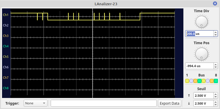
But the result doesn't seem okay ; here is the result of a simple low/high sequence feeded in USIDR (01010101) for 4 bytes :
(nota : i'm working on the source tree of Simulide-dev from github)
(nota 2 : the avr hex code is ok on a real Attiny85)
(nota 3 : of course on the circuit (real & virtual on Simulide), B0 pin is connected to a pullup resistor)
I hope this description can help.
Thank you !
Hi !
First of all, thank you for your work. I discovered SimulIDE about three weeks ago and I'm amazed by it.
I'm working with the USI module of the ATTiny85, clocked by the Timer0. I saw in the code you commented a line :
// TODO: setOutput(); at opposite edge, We need a falling edge...
(in avrusi.cpp / AvrUsi::callback() )
But the datasheet say :
When software strobe or Timer/Counter0 Compare Match clock option is selected, the output latch is
transparent and therefore the output is changed immediately. (p 117)
So i think there is no need of a falling edge : just a call to setOutput(). I modified the source code to make a try.
But the result doesn't seem okay ; here is the result of a simple low/high sequence feeded in USIDR (01010101) for 4 bytes :
(nota : i'm working on the source tree of Simulide-dev from github)
(nota 2 : the avr hex code is ok on a real Attiny85)
(nota 3 : of course on the circuit (real & virtual on Simulide), B0 pin is connected to a pullup resistor)
I hope this description can help.
Thank you !
Quote from Coethium on August 21, 2024, 11:07 amHi,
Here are the files.
Context : the aim is to make a 1-wire bus protocol with the USI in 2-wire mode ; but clocked with Timer0, not the CLK pin.
Nota 1 : I made some modifications in my firmware, now it sends 0x50555500. The LED on PB4 is simply a debug light (send data with usi (async) - LED on - wait 1s - LED off - wait 1s - loop).
Nota 2 : To see the wave i slow down the simulation (1000 steps/s = 0.1% speed)
Nota 3 : maybe there is a 2° bug : at the end of the process, I set USICR & USISR to 0. But the USI Counter does not stop. I saw in
AvrUsi::configureA() that when the mode (m_USIWM) is set to 0 ; the function is leaved before the configuration of the clock (so the clock isn't disabled in this case)130. if( !m_mode ) return; // DisabledI recommand to move this line after the configuration of the clock, to line 156.
Thank you !
Hi,
Here are the files.
Context : the aim is to make a 1-wire bus protocol with the USI in 2-wire mode ; but clocked with Timer0, not the CLK pin.
Nota 1 : I made some modifications in my firmware, now it sends 0x50555500. The LED on PB4 is simply a debug light (send data with usi (async) - LED on - wait 1s - LED off - wait 1s - loop).
Nota 2 : To see the wave i slow down the simulation (1000 steps/s = 0.1% speed)
Nota 3 : maybe there is a 2° bug : at the end of the process, I set USICR & USISR to 0. But the USI Counter does not stop. I saw in
AvrUsi::configureA() that when the mode (m_USIWM) is set to 0 ; the function is leaved before the configuration of the clock (so the clock isn't disabled in this case)
130. if( !m_mode ) return; // DisabledI recommand to move this line after the configuration of the clock, to line 156.
Thank you !
Uploaded files:Quote from arcachofo on August 21, 2024, 12:34 pmThanks.
I think I have an idea of what is happening, but it would be good to have the sketch to see how the timer is confugured and what is the program exactly doing.
Thanks.
I think I have an idea of what is happening, but it would be good to have the sketch to see how the timer is confugured and what is the program exactly doing.
Quote from Coethium on August 21, 2024, 2:00 pmHi !
Here is a sketch with the bare minimum to send 4 bytes (zipped because the forum doesn't allow .ino)
Thanks
Hi !
Here is a sketch with the bare minimum to send 4 bytes (zipped because the forum doesn't allow .ino)
Thanks
Uploaded files:Quote from arcachofo on August 21, 2024, 2:18 pmOk, thanks.
To make it work you can try to comment out line 152:
//m_t0OCB->getInterrupt()->callBack( this, timer );But this is something that is not completely clear to me.
When the datsheet says: "Timer/Counter0 Compare Match"
What exactly does it mean?
There are 2 Output Compare Units for Timer0...
Does it work only with Timer0 in CTC mode?
What happens in the real harware if you configure Timer0 to some other mode?
There are also a few other things to fix like the one you mentioned about disabling the USI.
Ok, thanks.
To make it work you can try to comment out line 152:
//m_t0OCB->getInterrupt()->callBack( this, timer );But this is something that is not completely clear to me.
When the datsheet says: "Timer/Counter0 Compare Match"
What exactly does it mean?
There are 2 Output Compare Units for Timer0...
Does it work only with Timer0 in CTC mode?
What happens in the real harware if you configure Timer0 to some other mode?
There are also a few other things to fix like the one you mentioned about disabling the USI.
Quote from Coethium on August 21, 2024, 2:57 pmHi,
With line 152 commented it seems to work ! Thanks.
About the datasheet : in the USI section, they only speak of "Timer/Counter0 Compare Match", without specifying A or B compare match.
But in the Timer0 section, we can see that the resolution/fréquency can only be driven by A :
I never tried with others modes, i will do some tests on real hardware and will give you the results.
Hi,
With line 152 commented it seems to work ! Thanks.
About the datasheet : in the USI section, they only speak of "Timer/Counter0 Compare Match", without specifying A or B compare match.
But in the Timer0 section, we can see that the resolution/fréquency can only be driven by A :
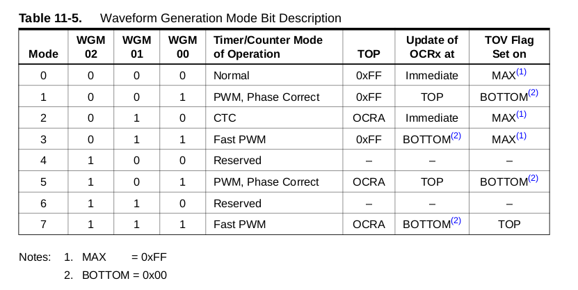
I never tried with others modes, i will do some tests on real hardware and will give you the results.
Quote from arcachofo on August 21, 2024, 3:22 pmIt would be great if you could do some test in real hardware.
It is not clear to me what exactly should trigger the USI:
- Only CTC.
- Any compare match A: USI should work with almost any T0 configuration
- Any T0 overflow triggered by a compare match A: USI would work with: 010 CTC, 101 PWM phase correct, 111 Fast PWM
It would be great if you could do some test in real hardware.
It is not clear to me what exactly should trigger the USI:
- Only CTC.
- Any compare match A: USI should work with almost any T0 configuration
- Any T0 overflow triggered by a compare match A: USI would work with: 010 CTC, 101 PWM phase correct, 111 Fast PWM
Quote from Coethium on August 21, 2024, 3:27 pmHi again,
On real hardware, with all others modes the Compare Match is raised for the USI. Of course, the Timer0 waveform is different, so the result in B0 is not the one expected. I just fast tested, without trying to finetuning. Do you need these tests results?
Compare Match B doesn't seems to be used to control the USI : i tried with OCR0B = OCR0A/2 (making the hypothesis of 2 Compare Matches in one cycle --> USI two times faster ?) ; and nothing change on B0, the speed is the same.
Hi again,
On real hardware, with all others modes the Compare Match is raised for the USI. Of course, the Timer0 waveform is different, so the result in B0 is not the one expected. I just fast tested, without trying to finetuning. Do you need these tests results?
Compare Match B doesn't seems to be used to control the USI : i tried with OCR0B = OCR0A/2 (making the hypothesis of 2 Compare Matches in one cycle --> USI two times faster ?) ; and nothing change on B0, the speed is the same.
Quote from arcachofo on August 21, 2024, 3:32 pmOk, thank you very much!
I think that clarifies everything: Compare match A always trigger the USI (but it is more practical to use CTC mode).
And that is good news, because then all what we need is to remove OCB from the USI .I will fix this and some other thing and commit it:
Nota 3 : maybe there is a 2° bug : at the end of the process, I set USICR & USISR to 0. But the USI Counter does not stop. I saw in
AvrUsi::configureA() that when the mode (m_USIWM) is set to 0 ; the function is leaved before the configuration of the clock (so the clock isn't disabled in this case)130. if( !m_mode ) return; // DisabledI recommand to move this line after the configuration of the clock, to line 156.
Ok, thank you very much!
I think that clarifies everything: Compare match A always trigger the USI (but it is more practical to use CTC mode).
And that is good news, because then all what we need is to remove OCB from the USI .
I will fix this and some other thing and commit it:
Nota 3 : maybe there is a 2° bug : at the end of the process, I set USICR & USISR to 0. But the USI Counter does not stop. I saw in
AvrUsi::configureA() that when the mode (m_USIWM) is set to 0 ; the function is leaved before the configuration of the clock (so the clock isn't disabled in this case)130. if( !m_mode ) return; // DisabledI recommand to move this line after the configuration of the clock, to line 156.