371_HC-05 BLUETOOTH COMMUNICATIONS

Quote from Defran on October 13, 2026, 7:15 am
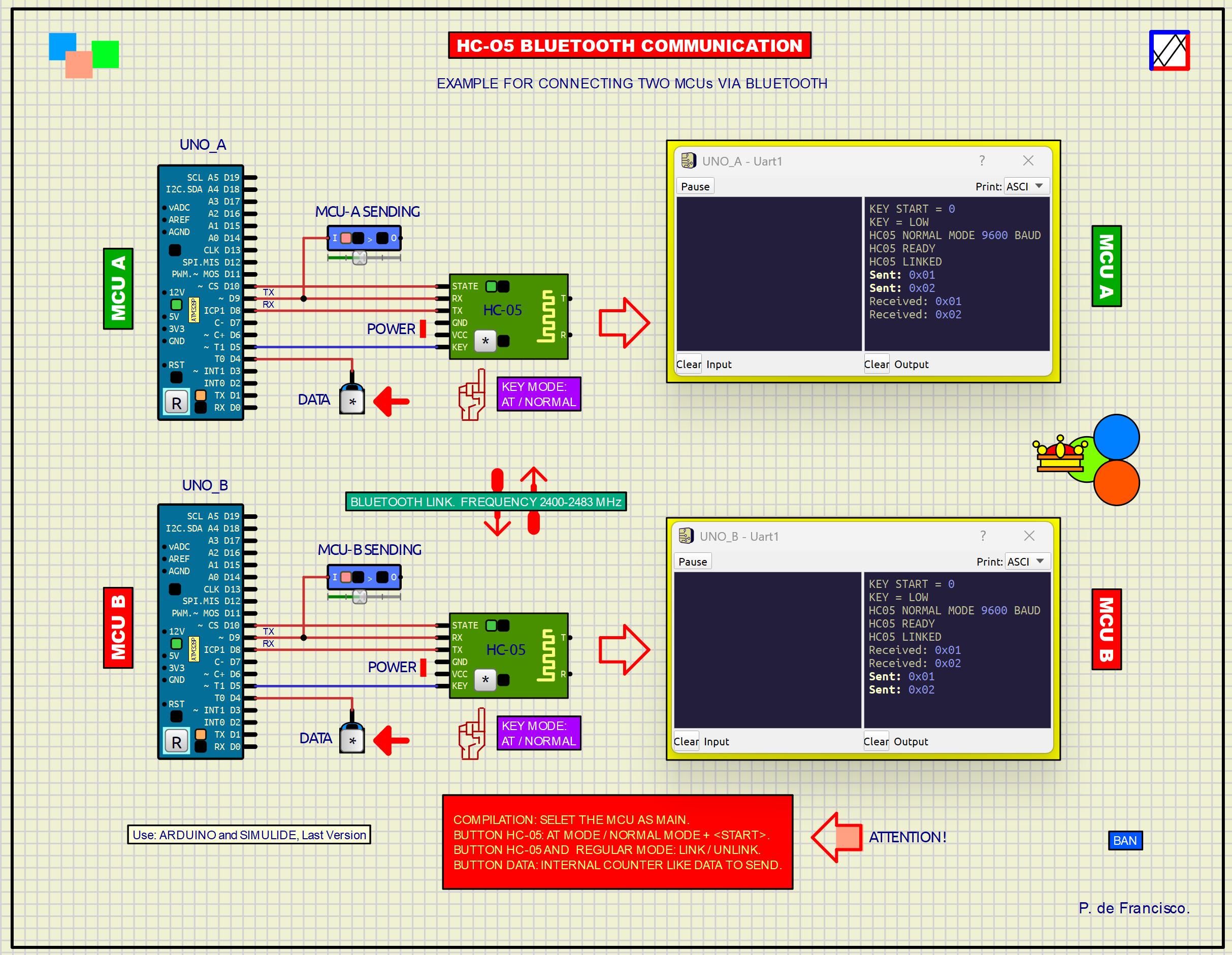
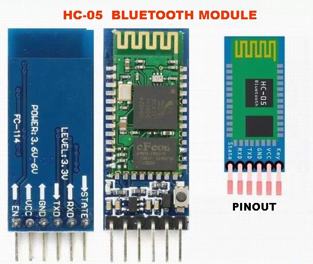
The HC-05 is a Bluetooth module widely used for sending and receiving data from an Arduino Uno via Bluetooth. It is also useful for communicating between two Arduino UNO, as in this example. From the Arduino, only the module and the data transmission processing are controlled. Physical communication between HC-05 modules occurs in their high-frequency stage. This is simulated here using Simulide's component linking capabilities. The HC-05 module is simulated using a script program in a subcircuit we have named HC_05.
The HC-05 has two operating modes: AT mode and NORMAL mode. AT mode is used to configure the module using AT commands, typical of serial communication: In our module, we have implemented the following commands:
AT Checks communication. Responds OK.
AT+NAME=HC-05 Assigns the module a name.
AT+NAME? Queryes its name.
AT+ROLE=0 Configures it as a slave, for connecting from an application.
AT+ROLE=1 Configures it as a master, for connecting to another module.
AT+ROLE? Checks the master or slave configuration.
AT+UART=9600,0,0 Configures the serial data port to 9600 baud, 8N1.
AT+UART? Checks the serial port configuration.
AT+PSWD=1234 Configures the password "1234".
AT+PSWD? Checks the password.
AT+STATE? Checks the pin state.Other useful but not implemented commands include:
AT+ADDR? Checks its own Bluetooth address.
AT+CMODE=0 Configures the master to connect to a specific destination.
AT+BIND=1234,56,ABCDEF Saves the destination's Bluetooth address.
AT+BIND? Checks the saved destination.There are more commands available online for use in the user program.
To enter AT mode, turn the module's KEY switch ON (GREEN LED OFF and RED LED ON), then deactivate and reactivate Simulide simulation. The commands will be displayed on the serial monitor of the corresponding MCU.
To enter NORMAL mode, turn the KEY switch OFF, which enters bidirectional data transmission mode (GREEN LED ON and RED LED OFF). It will display LINKED if paired with another module, and NO LINKED otherwise.In our example, the HC-05 module pins are connected to the Arduino pins according to the diagram of this example: Tx and RX are the communication pins, KEY (EN) changes the mode, and STATE displays the module's functional status. If working in NORMAL mode, switching the KEY to ON will disconnect the module, displaying "NO LINKED". In normal mode, each time the button on MCU_A is pressed, a count occurs. The data will be displayed on its monitor as sent and on MCU_B's monitor as received, and vice versa if the button on MCU_B is pressed. When a module receives data, its yellow LED flashes, provided both modules are paired.
To avoid errors, each screen of the serial monitor must be positioned correctly within its corresponding yellow rectangle, with MCU_A at the top and MCU_B at the bottom.
SCRIPT AND EXAMPLE PROGRAM:
The subcircuit script controls all processing to simulate the HC.05 module with added hardware to obtain the receive pulse displayed on the YELLOW LED. The application runs using the SoftwareSerial.h library, which allows you to edit the program by sending or receiving data.
// HC-05 - BLUETOOTH SCRIPT. DEFRAN26A
//
// RXD -> T
// R   -> TXD
//
// KEY LOW  = FUNCIONAMIENTO NORMAL
// KEY HIGH = MODO AT
//
// STATE HIGH = NORMAL
// STATE LOW  = AT
//
// MODO AT
// Velocidad AT = 38400 baudios
//
// Comandos:
// AT
// AT+NAME?
// AT+NAME=xxxxx
// AT+ROLE?
// AT+ROLE=0
// AT+ROLE=1
// AT+UART?
// AT+UART=9600,0,0
// AT+PSWD?
// AT+PSWD=1234
// AT+STATE?
// AT+RESET

IoPin@ pinRXD   = component.getPin("RXD");
IoPin@ pinTXD   = component.getPin("TXD");
IoPin@ pinR     = component.getPin("R");
IoPin@ pinT     = component.getPin("T");
IoPin@ pinKEY   = component.getPin("KEY");
IoPin@ pinSTATE = component.getPin("STATE");
const uint TICK_PS = 1000000;   // TEMPORIZACION 1 us
const uint BIT_TICKS = 26;      // Aproximadamente 38400 baudios
const uint FIRST_SAMPLE = 39;   // 1,5 bits
bool keyAnterior = false;  // CONTROL KEY
bool rxActivo = false;     // RECEPCION UART AT
uint rxContador = 0;
uint rxBit = 0;
uint rxDato = 0;
bool txActivo = false;  // TRANSMISION UART AT
uint txContador = 0;
uint txBit = 0;
uint txDato = 0;
string colaTX = "";
uint indiceTX = 0;
string comando = "";      // COMANDO RECIBIDO
string hcName = "HC-05";  // CONFIGURACION INTERNA HC-05
uint hcRole = 0;
string hcUART = "9600,0,0";
string hcPassword = "1234";

void setup()
{
  print("HC05 READY");
}

void limpiarAT()  // LIMPIAR ESTADO AT
{
  rxActivo = false;
  rxContador = 0;
  rxBit = 0;
  rxDato = 0;
  txActivo = false;
  txContador = 0;
  txBit = 0;
  txDato = 0;
  colaTX = "";
  indiceTX = 0;
  comando = "";
}

void reset()
{
  component.cancelEvents();
  pinRXD.setPinMode(1);  // ENTRADAS
  pinR.setPinMode(1);
  pinKEY.setPinMode(1);
  pinTXD.setPinMode(3);    // SALIDAS
  pinT.setPinMode(3);
  pinSTATE.setPinMode(3);
  pinTXD.setStateZ(false);    // Salidas activas
  pinT.setStateZ(false);
  pinSTATE.setStateZ(false);
  pinTXD.setVoltage(5.0);    // UART reposo HIGH
  pinT.setVoltage(5.0);
  limpiarAT();
  keyAnterior = pinKEY.getInpState();  // Estado inicial KEY
  if (keyAnterior)
  {
    pinSTATE.setVoltage(0.0);
    print("HC05 AT MODE 38400");
  }
  else
  {
    pinSTATE.setVoltage(5.0);
    print("HC05 NORMAL MODE");
  }
  component.addEvent(TICK_PS);
}

void enviarTexto(string texto)  // AÑADIR TEXTO A LA COLA AT
{
  colaTX += texto;
}

void responderOK()  // RESPUESTA OK
{
  enviarTexto("OK\r\n");
}

void responderERROR()  // RESPUESTA ERROR
{
  enviarTexto("ERROR\r\n");
}

void procesarComando()  // PROCESAR COMANDO AT
{
  print("HC05 RX: " + comando);
  if (comando == "AT") {responderOK();}  // AT
  else if (comando == "AT+NAME?")        // AT+NAME?
  {
    enviarTexto("+NAME:" + hcName + "\r\n");
    responderOK();
  }
  else if (comando.length() > 8 && comando.substr(0, 8) == "AT+NAME=")    // AT+NAME=
  {
    hcName = comando.substr(8);
    responderOK();
  }
  else if (comando == "AT+ROLE?")    // AT+ROLE?
  {
    if (hcRole == 0) {enviarTexto("+ROLE:0\r\n");}
    else {enviarTexto("+ROLE:1\r\n");}
    responderOK();
  }
  else if (comando == "AT+ROLE=0")    // AT+ROLE=0
  {
    hcRole = 0;
    responderOK();
  }
  else if (comando == "AT+ROLE=1")    // AT+ROLE=1
  {
    hcRole = 1;
    responderOK();
  }
  else if (comando == "AT+UART?")    // AT+UART?
  {
    enviarTexto("+UART:" + hcUART + "\r\n");
    responderOK();
  }
  else if (comando.length() > 8 && comando.substr(0, 8) == "AT+UART=")  // AT+UART=
  {
    hcUART = comando.substr(8);
    responderOK();
  }
  else if (comando == "AT+PSWD?")    // AT+PSWD?
  {
    enviarTexto("+PSWD:" + hcPassword + "\r\n");
    responderOK();
  }
  else if (comando.length() > 8 && comando.substr(0, 8) == "AT+PSWD=")  // AT+PSWD=
  {
    hcPassword = comando.substr(8);
    responderOK();
  }
  else if (comando == "AT+STATE?")  // AT+STATE?
  {
    enviarTexto("+STATE:INIT.\r\n");
    responderOK();
  }
  else if (comando == "AT+RESET") {responderOK();}   // AT+RESET
  else {responderERROR();}  // COMANDO DESCONOCIDO
  comando = "";
}

void byteRecibido(uint dato)  // BYTE AT RECIBIDO
{
  if (dato == 13) {return;}  // CR
  if (dato == 10)            // LF = FINAL DEL COMANDO
  {
    if (comando.length() > 0) {procesarComando();}
    return;
  }
  if (dato >= 32 && dato <= 126)  // CARACTER ASCII
  {
    // No admite: string(1, dato) Por eso cadena de 1 caracter y modificar directamente su byte [0].
    string caracter = " ";
    caracter[0] = uint8(dato);
    comando += caracter;
  }
}

void recibirUART()  // RECEPCION UART AT
{
  bool nivel = pinRXD.getVoltage() > 2.5;
  if (!rxActivo)    // ESPERAR START
  {
    if (!nivel)
    {
      rxActivo = true;
      rxContador = 0;
      rxBit = 0;
      rxDato = 0;
    }
    return;
  }
  rxContador++;
  if (rxBit == 0)    // PRIMER BIT DE DATOS
  {
    if (rxContador >= FIRST_SAMPLE)
    {
      if (nivel) {rxDato |= 1;}
      rxBit = 1;
      rxContador = 0;
    }
    return;
  }
  if (rxBit < 8)  // BITS 1..7
  {
    if (rxContador >= BIT_TICKS)
    {
      if (nivel) {rxDato |= (1 << rxBit);}
      rxBit++;
      rxContador = 0;
    }
    return;
  }
  if (rxContador >= BIT_TICKS)  // STOP
  {
    rxActivo = false;
    byteRecibido(rxDato);
    rxContador = 0;
    rxBit = 0;
    rxDato = 0;
  }
}

void iniciarByteTX(uint dato)  // INICIAR TRANSMISION DE UN BYTE AT
{
  txDato = dato;
  txActivo = true;
  txBit = 0;
  txContador = 0;
  pinTXD.setVoltage(0.0);  // START BIT
}

void transmitirUART()  // TRANSMISION UART AT
{
  if (!txActivo)  // BUSCAR SIGUIENTE CARACTER
  {
    if (indiceTX < colaTX.length())
    {
      uint dato = colaTX[indiceTX];
      indiceTX++;
      iniciarByteTX(dato);
    }
    else
    {
      colaTX = "";
      indiceTX = 0;
      pinTXD.setVoltage(5.0);
    }
    return;
  }
  txContador++;
  if (txContador < BIT_TICKS) {return;}
  txContador = 0;
  if (txBit < 8)    // BITS DE DATOS
  {
    bool nivel = (txDato & (1 << txBit)) != 0;
    if (nivel){pinTXD.setVoltage(5.0);}
    else {pinTXD.setVoltage(0.0);}
    txBit++;
    return;
  }
  if (txBit == 8)  // STOP BIT
  {
    pinTXD.setVoltage(5.0);
    txBit++;
    return;
  }
  txActivo = false;  // FIN DEL BYTE
  txBit = 0;
}

void runEvent()  // EVENTO PRINCIPAL
{
  bool key = pinKEY.getInpState();
  if (key != keyAnterior)    // CAMBIO DE KEY
  {
    limpiarAT();
    pinTXD.setVoltage(5.0);  // Reposo UART
    pinT.setVoltage(5.0);
    if (key)
    {
      pinSTATE.setVoltage(0.0);
      print("HC05 AT MODE 38400");
    }
    else
    {
      pinSTATE.setVoltage(5.0);
      print("HC05 NORMAL MODE");
    }
    keyAnterior = key;
  }
  if (!key)  // KEY LOW, FUNCIONAMIENTO NORMAL
  {
    pinSTATE.setVoltage(5.0);
    double vrxd = pinRXD.getVoltage();  // RXD -> T BLOQUE COMPROBADO QUE FUNCIONA EN SIMULIDE
    if (vrxd > 2.5) {pinT.setVoltage(5.0);}
    else {pinT.setVoltage(0.0);}
    double vr = pinR.getVoltage();  // R -> TXD
    if (vr > 2.5) {pinTXD.setVoltage(5.0);}
    else {pinTXD.setVoltage(0.0);}
    component.addEvent(TICK_PS);
    return;
  }
  pinSTATE.setVoltage(0.0);  // MODO AT. KEY HIGH
  pinT.setVoltage(5.0);      // Desconectar enlace R/T
  recibirUART();
  transmitirUART();
  component.addEvent(TICK_PS);
}

void voltChanged()  // CALLBACK
{
}
// ARDUINO UNO y HC-05. DEFRAN26A

// SoftwareSerial:
// Arduino D8 = RX  <- HC05 TXD
// Arduino D9 = TX  -> HC05 RXD
// HC-05:
// Arduino D5 = KEY
// Arduino D10 = STATE
// Arduino D4 -> pulsador -> GND
// KEY/D5 - 10K - GND, INTERRUPTOR +5V
// Al arrancar:
// KEY LOW  -> MODO NORMAL, 9600 baudios
// KEY HIGH -> MODO AT, 38400 baudios
/*  COMANDOS AT
AT
AT+NAME=HC-05
AT+ROLE=0
AT+UART=9600,0,0
AT+PSWD=1234
AT+NAME?
AT+ROLE?
AT+UART?
AT+PSWD?
AT+STATE?
*/

#include <SoftwareSerial.h>
SoftwareSerial BT(8, 9);   // RX, TX PUERTO SERIE HC-05
const byte BOTON = 4;
const byte KEY   = 5;
const byte STATE = 10;
const char NOMBRE_HC05[] = "HC-05";  // CONFIGURACION HC-05
const byte ROLE_HC05 = 0;  // 0 = SLAVE, 1 = MASTER
const long BAUD_NORMAL = 9600;
const char UART_HC05[] = "9600,0,0";  // 9600=velocidad, 0=1 bit de parada, 0=sin paridad
const char PASSWORD_HC05[] = "1234";
byte dato = 0x01;
bool estadoAnterior = HIGH;
bool stateAnterior = LOW;
bool keyAnterior = LOW;
bool modoAT = false;

bool leerKeyArranque()  // LEER KEY ESTABLE AL ARRANCAR, KEY en HIGH durante varias lecturas seguidas.
{
  byte altos = 0;  // Eliminar transitorio durante arranque evita modo AT.
  delay(300);      // Esperar estabilizacion circuito
  for (byte i=0; i<20; i++)  // 20 lecturas
  {
    if (digitalRead(KEY) == HIGH) {altos++;}
    delay(5);
  }
  if (altos >= 18) {return HIGH;}  // Entrada en AT, todas las lecturas HIGH.
  return LOW;
}

void leerRespuestaAT(unsigned long tiempo)  // LEER RESPUESTA AT
{
  unsigned long inicio = millis();
  while (millis() - inicio < tiempo) {while (BT.available()) {Serial.write(BT.read());}}
}

void enviarAT(const char *comando)  // ENVIAR COMANDO AT
{
  Serial.print(">> ");
  Serial.print(comando); Serial.write('\n');
  BT.println(comando);
  leerRespuestaAT(300);
}

void configurarHC05()  // CONFIGURAR HC-05
{
  char comando[40];
  Serial.print("---------------"); Serial.write('\n');  // SOLO LF, NO CR+LF
  Serial.print("HC05 AT CONFIG."); Serial.write('\n');
  Serial.print("---------------"); Serial.write('\n');
  enviarAT("AT");               // COMPROBAR COMUNICACION
  strcpy(comando, "AT+NAME=");  // NOMBRE
  strcat(comando, NOMBRE_HC05);
  enviarAT(comando);
  if (ROLE_HC05 == 0) {enviarAT("AT+ROLE=0");}  // ROLE
  else {enviarAT("AT+ROLE=1");}
  strcpy(comando, "AT+UART=");  // UART
  strcat(comando, UART_HC05);
  enviarAT(comando);
  strcpy(comando, "AT+PSWD=");  // PASSWORD
  strcat(comando, PASSWORD_HC05);
  enviarAT(comando);
  enviarAT("AT+NAME?");  // COMPROBAR CONFIGURACION
  enviarAT("AT+ROLE?");
  enviarAT("AT+UART?");
  enviarAT("AT+PSWD?");
  enviarAT("AT+STATE?");
  Serial.print("----------------");  Serial.write('\n');
  Serial.print("CONFIG. FINISHED");  Serial.write('\n');
  Serial.print("----------------");  Serial.write('\n');
  Serial.print("WAITING KEY LOW");   Serial.write('\n');
}

void setup()
{
  pinMode(BOTON, INPUT_PULLUP);
  pinMode(STATE, INPUT);
  pinMode(KEY, INPUT);  // KEY nunca desde Arduino. Siempre entrada externa.
  Serial.begin(9600);
  keyAnterior = leerKeyArranque();  // Leer KEY estable
  Serial.print("KEY START = ");
  Serial.print(keyAnterior); Serial.write('\n');
  if (keyAnterior == HIGH) {entrarModoAT();}  // Seleccion automatica
  else {entrarModoNormal();}
}

void loop()
{
  bool keyActual = digitalRead(KEY);  // LEER KEY
  if (modoAT && keyAnterior==HIGH && keyActual==LOW) {entrarModoNormal();}  // SALIR DEL MODO AT
  keyAnterior=keyActual;
  if (modoAT)  // MODO AT
  {
    while (BT.available()) {Serial.write(BT.read());}  // Si KEY en HIGH modo AT.
    return;
  }
  bool estadoState = digitalRead(STATE);  // STATE, FUNCIONAMIENTO NORMAL
  if (estadoState != stateAnterior)
  {
    if (estadoState == HIGH) {Serial.print("HC05 LINKED"); Serial.write('\n');}
    else {Serial.print("HC05 NOT LINKED"); Serial.write('\n');}
    stateAnterior = estadoState;
  }
  if (BT.available())  // RECEPCION
  {
    byte recibido = BT.read();
    char textoRX[20];
    sprintf(textoRX, "Received: 0x%02X", recibido);
    Serial.print(textoRX); Serial.write('\n');
  }
  bool estado = digitalRead(BOTON);  // PULSADOR
  if (estadoAnterior == HIGH && estado == LOW)  // Detectar pulsacion
  {
    BT.write(dato);   // TRANSMISION
    char textoTX[20];
    sprintf(textoTX, "Sent: 0x%02X", dato);
    Serial.print(textoTX); Serial.write('\n');
    dato++;       // SIGUIENTE DATO
    if (dato == 0x00) {dato = 0x01;}  // Evitar 0x00
    delay(30);    // ANTIRREBOTE
  }
  estadoAnterior = estado;
}

void limpiarBufferBT()  // LIMPIAR BUFFER BT
{
  while (BT.available()) {BT.read();}
}

void entrarModoNormal()  // ENTRAR EN MODO NORMAL
{
  limpiarBufferBT();  // Limpiar cualquier byte pendiente
  BT.end();
  delay(50);
  BT.begin(BAUD_NORMAL);
  delay(50);
  limpiarBufferBT();  // Limpiar otra vez por seguridad
  modoAT = false;
  Serial.print("KEY = LOW");  Serial.write('\n');
  Serial.print("HC05 NORMAL MODE ");
  Serial.print(BAUD_NORMAL);
  Serial.print(" BAUD");  Serial.write('\n');
  Serial.print("HC05 READY");  Serial.write('\n');
}

void entrarModoAT()  // ENTRAR EN MODO AT
{
  BT.end();
  delay(50);
  BT.begin(38400);
  modoAT = true;
  Serial.print("KEY = HIGH"); Serial.write('\n');
  Serial.print("HC05 AT MODE 38400"); Serial.write('\n');
  delay(300);
  configurarHC05();
}
CONTENTS
The contents of the ZIP package are as follows:
HC-05: Contains everything related to the subcircuit, including the necessary script files. If you wish to use this subcircuit yourself, you must add it to the Simulide menu, following its tutorials.HC-O5_Bluetooth_1 and HC-O5_Bluetooth_2 contain all the files for this example to function. Therefore, running sim1 or sim2 should work in your corresponding version of Simulide.
P. de Francisco.
The HC-05 is a Bluetooth module widely used for sending and receiving data from an Arduino Uno via Bluetooth. It is also useful for communicating between two Arduino UNO, as in this example. From the Arduino, only the module and the data transmission processing are controlled. Physical communication between HC-05 modules occurs in their high-frequency stage. This is simulated here using Simulide's component linking capabilities. The HC-05 module is simulated using a script program in a subcircuit we have named HC_05.
The HC-05 has two operating modes: AT mode and NORMAL mode. AT mode is used to configure the module using AT commands, typical of serial communication: In our module, we have implemented the following commands:
AT Checks communication. Responds OK.
AT+NAME=HC-05 Assigns the module a name.
AT+NAME? Queryes its name.
AT+ROLE=0 Configures it as a slave, for connecting from an application.
AT+ROLE=1 Configures it as a master, for connecting to another module.
AT+ROLE? Checks the master or slave configuration.
AT+UART=9600,0,0 Configures the serial data port to 9600 baud, 8N1.
AT+UART? Checks the serial port configuration.
AT+PSWD=1234 Configures the password "1234".
AT+PSWD? Checks the password.
AT+STATE? Checks the pin state.
Other useful but not implemented commands include:
AT+ADDR? Checks its own Bluetooth address.
AT+CMODE=0 Configures the master to connect to a specific destination.
AT+BIND=1234,56,ABCDEF Saves the destination's Bluetooth address.
AT+BIND? Checks the saved destination.
There are more commands available online for use in the user program.
To enter AT mode, turn the module's KEY switch ON (GREEN LED OFF and RED LED ON), then deactivate and reactivate Simulide simulation. The commands will be displayed on the serial monitor of the corresponding MCU.
To enter NORMAL mode, turn the KEY switch OFF, which enters bidirectional data transmission mode (GREEN LED ON and RED LED OFF). It will display LINKED if paired with another module, and NO LINKED otherwise.
In our example, the HC-05 module pins are connected to the Arduino pins according to the diagram of this example: Tx and RX are the communication pins, KEY (EN) changes the mode, and STATE displays the module's functional status. If working in NORMAL mode, switching the KEY to ON will disconnect the module, displaying "NO LINKED". In normal mode, each time the button on MCU_A is pressed, a count occurs. The data will be displayed on its monitor as sent and on MCU_B's monitor as received, and vice versa if the button on MCU_B is pressed. When a module receives data, its yellow LED flashes, provided both modules are paired.
To avoid errors, each screen of the serial monitor must be positioned correctly within its corresponding yellow rectangle, with MCU_A at the top and MCU_B at the bottom.
SCRIPT AND EXAMPLE PROGRAM:
The subcircuit script controls all processing to simulate the HC.05 module with added hardware to obtain the receive pulse displayed on the YELLOW LED. The application runs using the SoftwareSerial.h library, which allows you to edit the program by sending or receiving data.
// HC-05 - BLUETOOTH SCRIPT. DEFRAN26A
//
// RXD -> T
// R   -> TXD
//
// KEY LOW  = FUNCIONAMIENTO NORMAL
// KEY HIGH = MODO AT
//
// STATE HIGH = NORMAL
// STATE LOW  = AT
//
// MODO AT
// Velocidad AT = 38400 baudios
//
// Comandos:
// AT
// AT+NAME?
// AT+NAME=xxxxx
// AT+ROLE?
// AT+ROLE=0
// AT+ROLE=1
// AT+UART?
// AT+UART=9600,0,0
// AT+PSWD?
// AT+PSWD=1234
// AT+STATE?
// AT+RESET

IoPin@ pinRXD   = component.getPin("RXD");
IoPin@ pinTXD   = component.getPin("TXD");
IoPin@ pinR     = component.getPin("R");
IoPin@ pinT     = component.getPin("T");
IoPin@ pinKEY   = component.getPin("KEY");
IoPin@ pinSTATE = component.getPin("STATE");
const uint TICK_PS = 1000000;   // TEMPORIZACION 1 us
const uint BIT_TICKS = 26;      // Aproximadamente 38400 baudios
const uint FIRST_SAMPLE = 39;   // 1,5 bits
bool keyAnterior = false;  // CONTROL KEY
bool rxActivo = false;     // RECEPCION UART AT
uint rxContador = 0;
uint rxBit = 0;
uint rxDato = 0;
bool txActivo = false;  // TRANSMISION UART AT
uint txContador = 0;
uint txBit = 0;
uint txDato = 0;
string colaTX = "";
uint indiceTX = 0;
string comando = "";      // COMANDO RECIBIDO
string hcName = "HC-05";  // CONFIGURACION INTERNA HC-05
uint hcRole = 0;
string hcUART = "9600,0,0";
string hcPassword = "1234";

void setup()
{
  print("HC05 READY");
}

void limpiarAT()  // LIMPIAR ESTADO AT
{
  rxActivo = false;
  rxContador = 0;
  rxBit = 0;
  rxDato = 0;
  txActivo = false;
  txContador = 0;
  txBit = 0;
  txDato = 0;
  colaTX = "";
  indiceTX = 0;
  comando = "";
}

void reset()
{
  component.cancelEvents();
  pinRXD.setPinMode(1);  // ENTRADAS
  pinR.setPinMode(1);
  pinKEY.setPinMode(1);
  pinTXD.setPinMode(3);    // SALIDAS
  pinT.setPinMode(3);
  pinSTATE.setPinMode(3);
  pinTXD.setStateZ(false);    // Salidas activas
  pinT.setStateZ(false);
  pinSTATE.setStateZ(false);
  pinTXD.setVoltage(5.0);    // UART reposo HIGH
  pinT.setVoltage(5.0);
  limpiarAT();
  keyAnterior = pinKEY.getInpState();  // Estado inicial KEY
  if (keyAnterior)
  {
    pinSTATE.setVoltage(0.0);
    print("HC05 AT MODE 38400");
  }
  else
  {
    pinSTATE.setVoltage(5.0);
    print("HC05 NORMAL MODE");
  }
  component.addEvent(TICK_PS);
}

void enviarTexto(string texto)  // AÑADIR TEXTO A LA COLA AT
{
  colaTX += texto;
}

void responderOK()  // RESPUESTA OK
{
  enviarTexto("OK\r\n");
}

void responderERROR()  // RESPUESTA ERROR
{
  enviarTexto("ERROR\r\n");
}

void procesarComando()  // PROCESAR COMANDO AT
{
  print("HC05 RX: " + comando);
  if (comando == "AT") {responderOK();}  // AT
  else if (comando == "AT+NAME?")        // AT+NAME?
  {
    enviarTexto("+NAME:" + hcName + "\r\n");
    responderOK();
  }
  else if (comando.length() > 8 && comando.substr(0, 8) == "AT+NAME=")    // AT+NAME=
  {
    hcName = comando.substr(8);
    responderOK();
  }
  else if (comando == "AT+ROLE?")    // AT+ROLE?
  {
    if (hcRole == 0) {enviarTexto("+ROLE:0\r\n");}
    else {enviarTexto("+ROLE:1\r\n");}
    responderOK();
  }
  else if (comando == "AT+ROLE=0")    // AT+ROLE=0
  {
    hcRole = 0;
    responderOK();
  }
  else if (comando == "AT+ROLE=1")    // AT+ROLE=1
  {
    hcRole = 1;
    responderOK();
  }
  else if (comando == "AT+UART?")    // AT+UART?
  {
    enviarTexto("+UART:" + hcUART + "\r\n");
    responderOK();
  }
  else if (comando.length() > 8 && comando.substr(0, 8) == "AT+UART=")  // AT+UART=
  {
    hcUART = comando.substr(8);
    responderOK();
  }
  else if (comando == "AT+PSWD?")    // AT+PSWD?
  {
    enviarTexto("+PSWD:" + hcPassword + "\r\n");
    responderOK();
  }
  else if (comando.length() > 8 && comando.substr(0, 8) == "AT+PSWD=")  // AT+PSWD=
  {
    hcPassword = comando.substr(8);
    responderOK();
  }
  else if (comando == "AT+STATE?")  // AT+STATE?
  {
    enviarTexto("+STATE:INIT.\r\n");
    responderOK();
  }
  else if (comando == "AT+RESET") {responderOK();}   // AT+RESET
  else {responderERROR();}  // COMANDO DESCONOCIDO
  comando = "";
}

void byteRecibido(uint dato)  // BYTE AT RECIBIDO
{
  if (dato == 13) {return;}  // CR
  if (dato == 10)            // LF = FINAL DEL COMANDO
  {
    if (comando.length() > 0) {procesarComando();}
    return;
  }
  if (dato >= 32 && dato <= 126)  // CARACTER ASCII
  {
    // No admite: string(1, dato) Por eso cadena de 1 caracter y modificar directamente su byte [0].
    string caracter = " ";
    caracter[0] = uint8(dato);
    comando += caracter;
  }
}

void recibirUART()  // RECEPCION UART AT
{
  bool nivel = pinRXD.getVoltage() > 2.5;
  if (!rxActivo)    // ESPERAR START
  {
    if (!nivel)
    {
      rxActivo = true;
      rxContador = 0;
      rxBit = 0;
      rxDato = 0;
    }
    return;
  }
  rxContador++;
  if (rxBit == 0)    // PRIMER BIT DE DATOS
  {
    if (rxContador >= FIRST_SAMPLE)
    {
      if (nivel) {rxDato |= 1;}
      rxBit = 1;
      rxContador = 0;
    }
    return;
  }
  if (rxBit < 8)  // BITS 1..7
  {
    if (rxContador >= BIT_TICKS)
    {
      if (nivel) {rxDato |= (1 << rxBit);}
      rxBit++;
      rxContador = 0;
    }
    return;
  }
  if (rxContador >= BIT_TICKS)  // STOP
  {
    rxActivo = false;
    byteRecibido(rxDato);
    rxContador = 0;
    rxBit = 0;
    rxDato = 0;
  }
}

void iniciarByteTX(uint dato)  // INICIAR TRANSMISION DE UN BYTE AT
{
  txDato = dato;
  txActivo = true;
  txBit = 0;
  txContador = 0;
  pinTXD.setVoltage(0.0);  // START BIT
}

void transmitirUART()  // TRANSMISION UART AT
{
  if (!txActivo)  // BUSCAR SIGUIENTE CARACTER
  {
    if (indiceTX < colaTX.length())
    {
      uint dato = colaTX[indiceTX];
      indiceTX++;
      iniciarByteTX(dato);
    }
    else
    {
      colaTX = "";
      indiceTX = 0;
      pinTXD.setVoltage(5.0);
    }
    return;
  }
  txContador++;
  if (txContador < BIT_TICKS) {return;}
  txContador = 0;
  if (txBit < 8)    // BITS DE DATOS
  {
    bool nivel = (txDato & (1 << txBit)) != 0;
    if (nivel){pinTXD.setVoltage(5.0);}
    else {pinTXD.setVoltage(0.0);}
    txBit++;
    return;
  }
  if (txBit == 8)  // STOP BIT
  {
    pinTXD.setVoltage(5.0);
    txBit++;
    return;
  }
  txActivo = false;  // FIN DEL BYTE
  txBit = 0;
}

void runEvent()  // EVENTO PRINCIPAL
{
  bool key = pinKEY.getInpState();
  if (key != keyAnterior)    // CAMBIO DE KEY
  {
    limpiarAT();
    pinTXD.setVoltage(5.0);  // Reposo UART
    pinT.setVoltage(5.0);
    if (key)
    {
      pinSTATE.setVoltage(0.0);
      print("HC05 AT MODE 38400");
    }
    else
    {
      pinSTATE.setVoltage(5.0);
      print("HC05 NORMAL MODE");
    }
    keyAnterior = key;
  }
  if (!key)  // KEY LOW, FUNCIONAMIENTO NORMAL
  {
    pinSTATE.setVoltage(5.0);
    double vrxd = pinRXD.getVoltage();  // RXD -> T BLOQUE COMPROBADO QUE FUNCIONA EN SIMULIDE
    if (vrxd > 2.5) {pinT.setVoltage(5.0);}
    else {pinT.setVoltage(0.0);}
    double vr = pinR.getVoltage();  // R -> TXD
    if (vr > 2.5) {pinTXD.setVoltage(5.0);}
    else {pinTXD.setVoltage(0.0);}
    component.addEvent(TICK_PS);
    return;
  }
  pinSTATE.setVoltage(0.0);  // MODO AT. KEY HIGH
  pinT.setVoltage(5.0);      // Desconectar enlace R/T
  recibirUART();
  transmitirUART();
  component.addEvent(TICK_PS);
}

void voltChanged()  // CALLBACK
{
}
// ARDUINO UNO y HC-05. DEFRAN26A

// SoftwareSerial:
// Arduino D8 = RX  <- HC05 TXD
// Arduino D9 = TX  -> HC05 RXD
// HC-05:
// Arduino D5 = KEY
// Arduino D10 = STATE
// Arduino D4 -> pulsador -> GND
// KEY/D5 - 10K - GND, INTERRUPTOR +5V
// Al arrancar:
// KEY LOW  -> MODO NORMAL, 9600 baudios
// KEY HIGH -> MODO AT, 38400 baudios
/*  COMANDOS AT
AT
AT+NAME=HC-05
AT+ROLE=0
AT+UART=9600,0,0
AT+PSWD=1234
AT+NAME?
AT+ROLE?
AT+UART?
AT+PSWD?
AT+STATE?
*/

#include <SoftwareSerial.h>
SoftwareSerial BT(8, 9);   // RX, TX PUERTO SERIE HC-05
const byte BOTON = 4;
const byte KEY   = 5;
const byte STATE = 10;
const char NOMBRE_HC05[] = "HC-05";  // CONFIGURACION HC-05
const byte ROLE_HC05 = 0;  // 0 = SLAVE, 1 = MASTER
const long BAUD_NORMAL = 9600;
const char UART_HC05[] = "9600,0,0";  // 9600=velocidad, 0=1 bit de parada, 0=sin paridad
const char PASSWORD_HC05[] = "1234";
byte dato = 0x01;
bool estadoAnterior = HIGH;
bool stateAnterior = LOW;
bool keyAnterior = LOW;
bool modoAT = false;

bool leerKeyArranque()  // LEER KEY ESTABLE AL ARRANCAR, KEY en HIGH durante varias lecturas seguidas.
{
  byte altos = 0;  // Eliminar transitorio durante arranque evita modo AT.
  delay(300);      // Esperar estabilizacion circuito
  for (byte i=0; i<20; i++)  // 20 lecturas
  {
    if (digitalRead(KEY) == HIGH) {altos++;}
    delay(5);
  }
  if (altos >= 18) {return HIGH;}  // Entrada en AT, todas las lecturas HIGH.
  return LOW;
}

void leerRespuestaAT(unsigned long tiempo)  // LEER RESPUESTA AT
{
  unsigned long inicio = millis();
  while (millis() - inicio < tiempo) {while (BT.available()) {Serial.write(BT.read());}}
}

void enviarAT(const char *comando)  // ENVIAR COMANDO AT
{
  Serial.print(">> ");
  Serial.print(comando); Serial.write('\n');
  BT.println(comando);
  leerRespuestaAT(300);
}

void configurarHC05()  // CONFIGURAR HC-05
{
  char comando[40];
  Serial.print("---------------"); Serial.write('\n');  // SOLO LF, NO CR+LF
  Serial.print("HC05 AT CONFIG."); Serial.write('\n');
  Serial.print("---------------"); Serial.write('\n');
  enviarAT("AT");               // COMPROBAR COMUNICACION
  strcpy(comando, "AT+NAME=");  // NOMBRE
  strcat(comando, NOMBRE_HC05);
  enviarAT(comando);
  if (ROLE_HC05 == 0) {enviarAT("AT+ROLE=0");}  // ROLE
  else {enviarAT("AT+ROLE=1");}
  strcpy(comando, "AT+UART=");  // UART
  strcat(comando, UART_HC05);
  enviarAT(comando);
  strcpy(comando, "AT+PSWD=");  // PASSWORD
  strcat(comando, PASSWORD_HC05);
  enviarAT(comando);
  enviarAT("AT+NAME?");  // COMPROBAR CONFIGURACION
  enviarAT("AT+ROLE?");
  enviarAT("AT+UART?");
  enviarAT("AT+PSWD?");
  enviarAT("AT+STATE?");
  Serial.print("----------------");  Serial.write('\n');
  Serial.print("CONFIG. FINISHED");  Serial.write('\n');
  Serial.print("----------------");  Serial.write('\n');
  Serial.print("WAITING KEY LOW");   Serial.write('\n');
}

void setup()
{
  pinMode(BOTON, INPUT_PULLUP);
  pinMode(STATE, INPUT);
  pinMode(KEY, INPUT);  // KEY nunca desde Arduino. Siempre entrada externa.
  Serial.begin(9600);
  keyAnterior = leerKeyArranque();  // Leer KEY estable
  Serial.print("KEY START = ");
  Serial.print(keyAnterior); Serial.write('\n');
  if (keyAnterior == HIGH) {entrarModoAT();}  // Seleccion automatica
  else {entrarModoNormal();}
}

void loop()
{
  bool keyActual = digitalRead(KEY);  // LEER KEY
  if (modoAT && keyAnterior==HIGH && keyActual==LOW) {entrarModoNormal();}  // SALIR DEL MODO AT
  keyAnterior=keyActual;
  if (modoAT)  // MODO AT
  {
    while (BT.available()) {Serial.write(BT.read());}  // Si KEY en HIGH modo AT.
    return;
  }
  bool estadoState = digitalRead(STATE);  // STATE, FUNCIONAMIENTO NORMAL
  if (estadoState != stateAnterior)
  {
    if (estadoState == HIGH) {Serial.print("HC05 LINKED"); Serial.write('\n');}
    else {Serial.print("HC05 NOT LINKED"); Serial.write('\n');}
    stateAnterior = estadoState;
  }
  if (BT.available())  // RECEPCION
  {
    byte recibido = BT.read();
    char textoRX[20];
    sprintf(textoRX, "Received: 0x%02X", recibido);
    Serial.print(textoRX); Serial.write('\n');
  }
  bool estado = digitalRead(BOTON);  // PULSADOR
  if (estadoAnterior == HIGH && estado == LOW)  // Detectar pulsacion
  {
    BT.write(dato);   // TRANSMISION
    char textoTX[20];
    sprintf(textoTX, "Sent: 0x%02X", dato);
    Serial.print(textoTX); Serial.write('\n');
    dato++;       // SIGUIENTE DATO
    if (dato == 0x00) {dato = 0x01;}  // Evitar 0x00
    delay(30);    // ANTIRREBOTE
  }
  estadoAnterior = estado;
}

void limpiarBufferBT()  // LIMPIAR BUFFER BT
{
  while (BT.available()) {BT.read();}
}

void entrarModoNormal()  // ENTRAR EN MODO NORMAL
{
  limpiarBufferBT();  // Limpiar cualquier byte pendiente
  BT.end();
  delay(50);
  BT.begin(BAUD_NORMAL);
  delay(50);
  limpiarBufferBT();  // Limpiar otra vez por seguridad
  modoAT = false;
  Serial.print("KEY = LOW");  Serial.write('\n');
  Serial.print("HC05 NORMAL MODE ");
  Serial.print(BAUD_NORMAL);
  Serial.print(" BAUD");  Serial.write('\n');
  Serial.print("HC05 READY");  Serial.write('\n');
}

void entrarModoAT()  // ENTRAR EN MODO AT
{
  BT.end();
  delay(50);
  BT.begin(38400);
  modoAT = true;
  Serial.print("KEY = HIGH"); Serial.write('\n');
  Serial.print("HC05 AT MODE 38400"); Serial.write('\n');
  delay(300);
  configurarHC05();
}
CONTENTS
The contents of the ZIP package are as follows:
HC-05: Contains everything related to the subcircuit, including the necessary script files. If you wish to use this subcircuit yourself, you must add it to the Simulide menu, following its tutorials.
HC-O5_Bluetooth_1 and HC-O5_Bluetooth_2 contain all the files for this example to function. Therefore, running sim1 or sim2 should work in your corresponding version of Simulide.
P. de Francisco.
Uploaded files: