
DS18B20 sensor throwing ROM command Not implemented warning (version 1.1.0 RC1 R2162 Win x64)

Quote from Cemenotar on January 28, 2024, 6:15 pmThe first problem I found is that there is no pullup resistor and seems that the atmega328 internal pullup is not activated.
I hope this will not sound like a stupid question, but is this something I should do in the code, that I didn't or is that something to be set within simulation? In either case what would be recommended way to fix that issue?
The first problem I found is that there is no pullup resistor and seems that the atmega328 internal pullup is not activated.
I hope this will not sound like a stupid question, but is this something I should do in the code, that I didn't or is that something to be set within simulation? In either case what would be recommended way to fix that issue?
Quote from Cemenotar on January 28, 2024, 6:17 pmQuote from arcachofo on January 28, 2024, 6:10 pmWhere can I find this logic analizer?
Thank you, I was looking for it in apparently very wrong section of the list, and the search fuction does not seem to be working in the way I was trying to use it 🙂
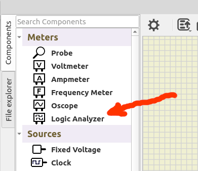
Quote from arcachofo on January 28, 2024, 6:10 pmWhere can I find this logic analizer?
Thank you, I was looking for it in apparently very wrong section of the list, and the search fuction does not seem to be working in the way I was trying to use it 🙂
Quote from arcachofo on January 28, 2024, 6:25 pmAll depends on the implementation of the library and I'm not an expert in 1 wire protocol.
It can be implemented in a way that needs an external pullup resistor or in a way that uses the internal pullup.But in any case I think it should never do a HIGH state by setting a pin to Output with PORT bit = 1.
A High state can be done by pin to Input + PORT bit = 1 (use internal pullup).
A Low state by: pin to Output + PORT bit = 0.Or keep PORT bit = 0 always, and use an external pullup resistor. Then:
A High state by: pin to Input (use external pullup).
A Low state by: pin to Output.
All depends on the implementation of the library and I'm not an expert in 1 wire protocol.
It can be implemented in a way that needs an external pullup resistor or in a way that uses the internal pullup.
But in any case I think it should never do a HIGH state by setting a pin to Output with PORT bit = 1.
A High state can be done by pin to Input + PORT bit = 1 (use internal pullup).
A Low state by: pin to Output + PORT bit = 0.
Or keep PORT bit = 0 always, and use an external pullup resistor. Then:
A High state by: pin to Input (use external pullup).
A Low state by: pin to Output.
Quote from Cemenotar on January 28, 2024, 6:37 pmI am now mildly confused, because both of the libraries used use both DDR and PORT registers to put high/low state which by your description should mean they are activating the internal resistor as needed..... in the meantime I have also looked at the code of the bigger library, and the handling of writing commands do seem mildly weird, it starts with putting the pin in high state, and then "write" high by pulling it to low for less than a certain window of time and "write" low by putting low for longer period.
and it does indeed never put it low again.
There is also a topic of sensors using parasitic power and the less complex library had comment from one of users, that in parasitic power mode, if the pin is set to low for whole conversion process it looses power before it can finish, for which they recomended a "fix" of putting the pin in high for the duration of conversion.
I am now mildly confused, because both of the libraries used use both DDR and PORT registers to put high/low state which by your description should mean they are activating the internal resistor as needed..... in the meantime I have also looked at the code of the bigger library, and the handling of writing commands do seem mildly weird, it starts with putting the pin in high state, and then "write" high by pulling it to low for less than a certain window of time and "write" low by putting low for longer period.
and it does indeed never put it low again.
There is also a topic of sensors using parasitic power and the less complex library had comment from one of users, that in parasitic power mode, if the pin is set to low for whole conversion process it looses power before it can finish, for which they recomended a "fix" of putting the pin in high for the duration of conversion.
Quote from arcachofo on January 28, 2024, 6:45 pmboth of the libraries used use both DDR and PORT registers to put high/low state which by your description should mean they are activating the internal resistor as needed
The fact that they use DDR and PORT does not necessarily mean that they use internal pullup.
Indeed, for what I see, the library in the first example needs an external pullup resistor.
If you add it, you will not get the ROM command warning.That library after Reset, configure the pin as Output but set state to Low:
void gset_input_hiz(const gpin_t* pin) {
    *(pin->ddr) &= ~_BV(pin->bit);
    gset_output_low(pin);
}
It could use the internal pullup, but it does not:
void gset_input_pullup(const gpin_t* pin) {
    *(pin->ddr) &= ~_BV(pin->bit);
    gset_output_high(pin);
}
There are multiple ways to implement those libraries.
both of the libraries used use both DDR and PORT registers to put high/low state which by your description should mean they are activating the internal resistor as needed
The fact that they use DDR and PORT does not necessarily mean that they use internal pullup.
Indeed, for what I see, the library in the first example needs an external pullup resistor.
If you add it, you will not get the ROM command warning.
That library after Reset, configure the pin as Output but set state to Low:
void gset_input_hiz(const gpin_t* pin) {
    *(pin->ddr) &= ~_BV(pin->bit);
    gset_output_low(pin);
}
It could use the internal pullup, but it does not:
void gset_input_pullup(const gpin_t* pin) {
    *(pin->ddr) &= ~_BV(pin->bit);
    gset_output_high(pin);
}
There are multiple ways to implement those libraries.
Quote from arcachofo on January 28, 2024, 6:55 pmit starts with putting the pin in high state, and then "write" high by pulling it to low for less than a certain window of time and "write" low by putting low for longer period.
I don't remember much about the 1 wire protocol, but for what I see in the code in simulide that is the case: long pulse = 0, short pulse = 1.
and it does indeed never put it low again.
Yes, that is right, I didn't remember it and saw the line low at the beginning and High at the end...
But when the line is "free" should be High.
it starts with putting the pin in high state, and then "write" high by pulling it to low for less than a certain window of time and "write" low by putting low for longer period.
I don't remember much about the 1 wire protocol, but for what I see in the code in simulide that is the case: long pulse = 0, short pulse = 1.
and it does indeed never put it low again.
Yes, that is right, I didn't remember it and saw the line low at the beginning and High at the end...
But when the line is "free" should be High.
Quote from Cemenotar on January 28, 2024, 7:02 pmthank you very much, after switching back again to the first library, and adding external pull up resistor - like on the following picture:
I am no longer getting ROM errors, and also I am receiving the correct readings on the display.
thank you very much, after switching back again to the first library, and adding external pull up resistor - like on the following picture:
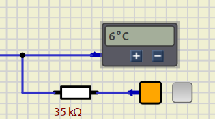
I am no longer getting ROM errors, and also I am receiving the correct readings on the display.