Attiny85 USI I2C
Quote from steinm on January 8, 2024, 7:17 amRev 2133 is working a lot better and I did some initial tests to talk to a SSD1306 Oled. Well, it's not working (at least there is no visible output) but the TWI protocol seems to be ok.
This is the start of the initialization sequence. There is a glitch on the SDA line at the end of the first command, but that may not be problematic. The sequence of commands is just like expected. I need to recheck if my code runs on real hardware. Is SSD1306 a good choice for testing? Is it known to work? Are there other parts that could be used for testing?
Rev 2133 is working a lot better and I did some initial tests to talk to a SSD1306 Oled. Well, it's not working (at least there is no visible output) but the TWI protocol seems to be ok.

This is the start of the initialization sequence. There is a glitch on the SDA line at the end of the first command, but that may not be problematic. The sequence of commands is just like expected. I need to recheck if my code runs on real hardware. Is SSD1306 a good choice for testing? Is it known to work? Are there other parts that could be used for testing?
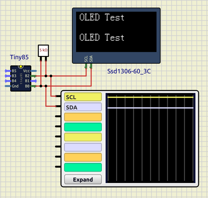
Quote from arcachofo on January 8, 2024, 7:44 amI tested a simple example with SSD1306 and it's working for me:
There are some other components using I2C, for example I2C RAM, I2C to Parallel, AIP31068 LCD, DS1306 RTC, DS1621 Temp. sensor, Microcontrllers with TWI, and even custom script components can use I2C.
EDIT: are you sure that the address is correct?
I tested a simple example with SSD1306 and it's working for me:

There are some other components using I2C, for example I2C RAM, I2C to Parallel, AIP31068 LCD, DS1306 RTC, DS1621 Temp. sensor, Microcontrllers with TWI, and even custom script components can use I2C.
EDIT: are you sure that the address is correct?
Quote from Defran on January 8, 2024, 8:09 amWell, the most important thing is that the Tiny85 works with the OLED, this gives it immense practical use, thank you very much, you are CHAMPIONS, CONGRATULATIONS.
Question: Would this also apply to the other useful Tiny, such as Tiny84?
Well, the most important thing is that the Tiny85 works with the OLED, this gives it immense practical use, thank you very much, you are CHAMPIONS, CONGRATULATIONS.
Question: Would this also apply to the other useful Tiny, such as Tiny84?
Quote from steinm on January 10, 2024, 6:41 pmLooks like there is still a minor issue in the USI code which disables the pwm output on PB1 timer1 is configure like this
  DDRB |= (1 << PB1); // PWM as output
  GTCCR |= (1 << PSR1);
  TCCR1 = 1 << PWM1A | 1 << COM1A1 | /* 1 << COM1A0 | */ 1 << CS12 | 1 << CS11 | 1 << CS10;
  TCNT1=0x00;
  OCR1A = 0xA0;
  OCR1C = 0xFF;
PB1 (OC1A) is the output the pwm signal, but it remains high all the time. After some debugging I found
USICR  =  (0<<USISIE)|(0<<USIOIE)|                  // Disable Interrupts.
          (1<<USIWM1)|(0<<USIWM0)|                  // Set USI in Two-wire mode.
          (1<<USICS1)|(0<<USICS0)|(1<<USICLK)|      // Software stobe as counter clock source
          (0<<USITC);
to be the reason. I suppose it manipulates PORTB in some way which turns the pwm signal off. I can still toggle PB1 but the pwm signal will only reappear if USICR isn't set.
Looks like there is still a minor issue in the USI code which disables the pwm output on PB1 timer1 is configure like this
  DDRB |= (1 << PB1); // PWM as output
  GTCCR |= (1 << PSR1);
  TCCR1 = 1 << PWM1A | 1 << COM1A1 | /* 1 << COM1A0 | */ 1 << CS12 | 1 << CS11 | 1 << CS10;
  TCNT1=0x00;
  OCR1A = 0xA0;
  OCR1C = 0xFF;
PB1 (OC1A) is the output the pwm signal, but it remains high all the time. After some debugging I found
USICR  =  (0<<USISIE)|(0<<USIOIE)|                  // Disable Interrupts.
          (1<<USIWM1)|(0<<USIWM0)|                  // Set USI in Two-wire mode.
          (1<<USICS1)|(0<<USICS0)|(1<<USICLK)|      // Software stobe as counter clock source
          (0<<USITC);
to be the reason. I suppose it manipulates PORTB in some way which turns the pwm signal off. I can still toggle PB1 but the pwm signal will only reappear if USICR isn't set.
Quote from arcachofo on January 11, 2024, 6:09 amLooks like there is still a minor issue in the USI code which disables the pwm output on PB1 timer1
Solved at Rev 2136.
Looks like there is still a minor issue in the USI code which disables the pwm output on PB1 timer1
Solved at Rev 2136.
