Arduino serial monitor in 1.1.0SR0 Rev 2278
Quote from Ldntech on April 2, 2024, 7:36 amHello,
The issue concerns the serial monitor used in Arduino simulation. The input field for entering the string of characters and the button for the end-of-line termination that were present in the previous version are now missing. I've tested it on multiple PCs, and the same issue persists.
Hello,
The issue concerns the serial monitor used in Arduino simulation. The input field for entering the string of characters and the button for the end-of-line termination that were present in the previous version are now missing. I've tested it on multiple PCs, and the same issue persists.
Quote from arcachofo on April 2, 2024, 11:10 amHi, thanks for reporting.
The input field for entering the string of characters and the button for the end-of-line termination that were present in the previous version are now missing.
Yes, now the serial monitor just shows the data in and out:
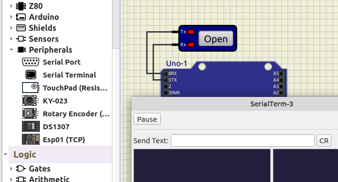
https://simulide.com/p/serial-monitor/To send data to the Arduino in 1.1.0 you need to connect a "Serial Terminal" (Micro->Peripherals).
Click "Open" in Serial Terminal and send data from there:
Hi, thanks for reporting.
The input field for entering the string of characters and the button for the end-of-line termination that were present in the previous version are now missing.
Yes, now the serial monitor just shows the data in and out:
https://simulide.com/p/serial-monitor/
To send data to the Arduino in 1.1.0 you need to connect a "Serial Terminal" (Micro->Peripherals).
Click "Open" in Serial Terminal and send data from there:

Quote from Ldntech on April 2, 2024, 11:51 amThank you very much for the response, it works very well.
It is necessary to configure the terminal port in the properties, otherwise it won't work and that's normal.
I'm really impressed by the capabilities of the software.
I presented it to my daughter's teacher so that he could use it in class.
He asked if we could have both terminals in the current and voltage sources.
I don't think so, but there might be a way.
Thank you very much for the response, it works very well.
It is necessary to configure the terminal port in the properties, otherwise it won't work and that's normal.
I'm really impressed by the capabilities of the software.
I presented it to my daughter's teacher so that he could use it in class.
He asked if we could have both terminals in the current and voltage sources.
I don't think so, but there might be a way.
Quote from arcachofo on April 2, 2024, 12:28 pmNice to know you got it working (and found the configuration).
He asked if we could have both terminals in the current and voltage sources.
Voltage and Current sources are refered to ground and there is no way to change it.
But it is posible to do what he wants with a controlled source.Add a Controlled Source to the circuit, open properties dialog and:
1- Check/Unchek "Current Source" to configure as Current or Voltage source.
2- Uncheck "Use control Pins". Now you have a fixed value source.
3- Set value for Voltage or current.To make a variable source:
You can control the source with a Dial component (almost at the end of the list), but it takes a bit of configuration:
1- Right-click on the Dial and select "Link to component" in the context menu (cursor will change).
2- Click on the source (it will become blue).
3- Click on any empty part of the circuit.
Now the dial is controlling the source.
By default the dial sends values 0 to 1000.
Open Dial properties and set "Maximum Value" to what you want, for exanple 5 for 5 V or 5 A.You can embed this variable source in a Subcircuit and create a new component.
Nice to know you got it working (and found the configuration).
He asked if we could have both terminals in the current and voltage sources.
Voltage and Current sources are refered to ground and there is no way to change it.
But it is posible to do what he wants with a controlled source.
Add a Controlled Source to the circuit, open properties dialog and:
1- Check/Unchek "Current Source" to configure as Current or Voltage source.
2- Uncheck "Use control Pins". Now you have a fixed value source.
3- Set value for Voltage or current.
To make a variable source:
You can control the source with a Dial component (almost at the end of the list), but it takes a bit of configuration:
1- Right-click on the Dial and select "Link to component" in the context menu (cursor will change).
2- Click on the source (it will become blue).
3- Click on any empty part of the circuit.
Now the dial is controlling the source.
By default the dial sends values 0 to 1000.
Open Dial properties and set "Maximum Value" to what you want, for exanple 5 for 5 V or 5 A.
You can embed this variable source in a Subcircuit and create a new component.
Quote from Ldntech on April 30, 2024, 1:53 pmThank you for the informations
I'm going to try creating a subcircuit as soon as I've a moment.
Thank you for the informations
I'm going to try creating a subcircuit as soon as I've a moment.
