
Alternating voltage and phase shift
Quote from feri on February 1, 2025, 3:37 pmI'm doing some tests with alternating current to simulate the phase shift with inductance and capacitance.
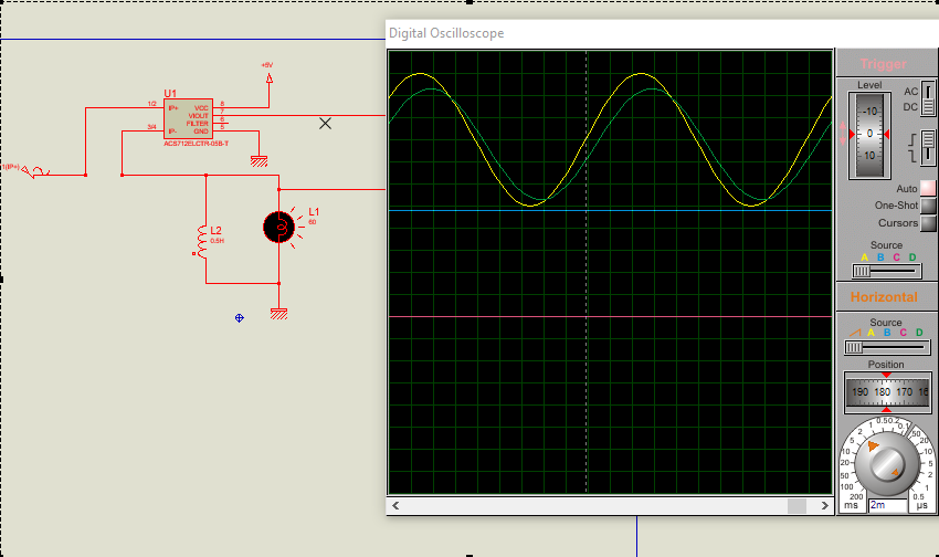
If I put a capacitor in parallel to the transformer the waveform becomes strange.
This is how it should be, I attach an image.
Greetings.
I'm doing some tests with alternating current to simulate the phase shift with inductance and capacitance.
If I put a capacitor in parallel to the transformer the waveform becomes strange.
This is how it should be, I attach an image.
Greetings.
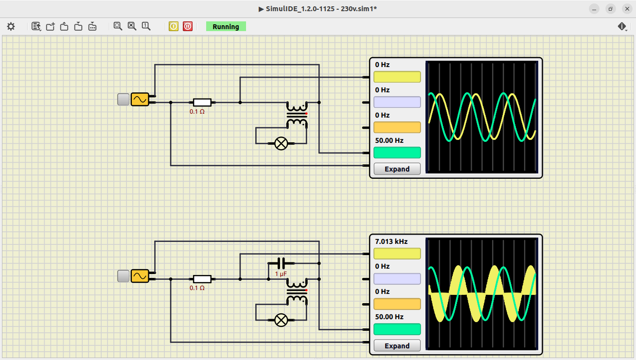
Quote from feri on February 3, 2025, 2:45 pmThe strange waveform was solved by bringing Reactive step 0 us to Reactive step 10000 us. the transformer phase shifts the voltage and current and by inserting a capacitor in parallel of a certain capacity the voltage and current return to phase.
I don't know if the values correspond to reality but the principle is correct.
The capacitor in parallel with a resistive load should phase shift the current and voltage in the opposite way to the transformer.
In my test circuit the voltage and current remain in phase.
The strange waveform was solved by bringing Reactive step 0 us to Reactive step 10000 us. the transformer phase shifts the voltage and current and by inserting a capacitor in parallel of a certain capacity the voltage and current return to phase.
I don't know if the values correspond to reality but the principle is correct.
The capacitor in parallel with a resistive load should phase shift the current and voltage in the opposite way to the transformer.
In my test circuit the voltage and current remain in phase.
Uploaded files: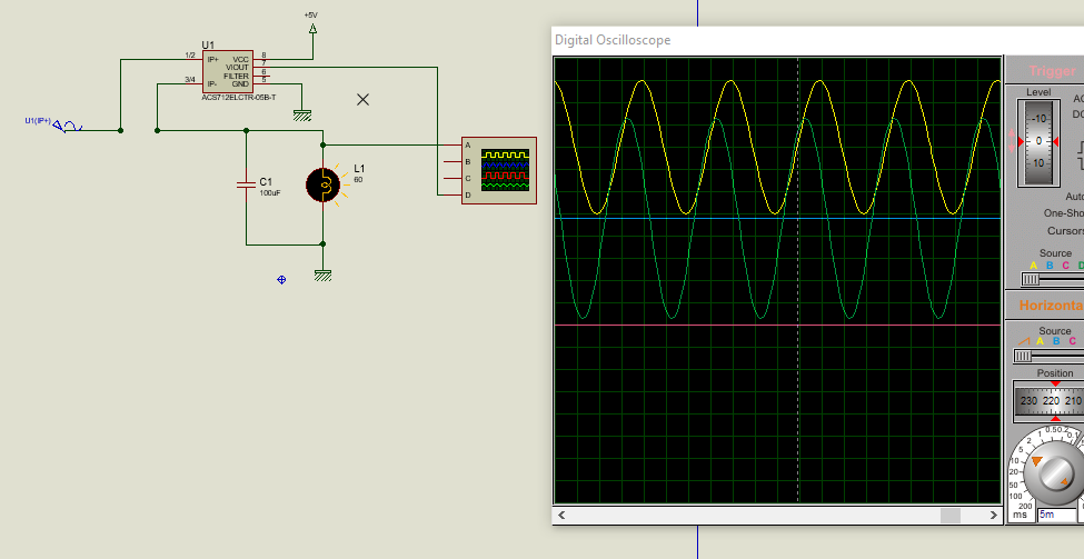
Quote from average_simulide_enjoyer on February 6, 2025, 10:03 pmIf im not sure, reactive step of 0 (no matter the unit) means there's NO REACTIVE STEP
A capacitor (and inductor iirc) requires reactive step to be simulated minimally accurately.
Thays why it got fixed by U setting reactive step to non 0. But now it begs the question. Why was ur reactive step 0? Iirc, it is by default like 1000 μs or something.
Anyways, making that number even smaller (like 1ns) will get u more accurate results at the cost of more accurate waves, and consequently simulation time
If im not sure, reactive step of 0 (no matter the unit) means there's NO REACTIVE STEP
A capacitor (and inductor iirc) requires reactive step to be simulated minimally accurately.
Thays why it got fixed by U setting reactive step to non 0. But now it begs the question. Why was ur reactive step 0? Iirc, it is by default like 1000 μs or something.
Anyways, making that number even smaller (like 1ns) will get u more accurate results at the cost of more accurate waves, and consequently simulation time
Quote from arcachofo on February 6, 2025, 11:18 pmIf im not sure, reactive step of 0 (no matter the unit) means there's NO REACTIVE STEP
Indeed it means no custom reactive step: use the global value, which can be configured in simulation settings (default 1 us).
As you mention, some reactive step is needed to simulate reactive components.The problem in this case is about synchronization with the sine wave.
Even if you use the same step in sine wave and capacitor there are some spikes.
Btw, I didn't forget about this, still thinking in some solution.
If im not sure, reactive step of 0 (no matter the unit) means there's NO REACTIVE STEP
Indeed it means no custom reactive step: use the global value, which can be configured in simulation settings (default 1 us).
As you mention, some reactive step is needed to simulate reactive components.
The problem in this case is about synchronization with the sine wave.
Even if you use the same step in sine wave and capacitor there are some spikes.
Btw, I didn't forget about this, still thinking in some solution.
Quote from arcachofo on April 26, 2025, 2:32 pmFor version 1.1.0, the synchronization is improved, but you need to set the step of the wave and reactive step to be the same duration.
In 1.2.0 there is a new way to deal with this and it should be always synchronized.
For version 1.1.0, the synchronization is improved, but you need to set the step of the wave and reactive step to be the same duration.
In 1.2.0 there is a new way to deal with this and it should be always synchronized.