372_ MPU6050 GYROSCOPE AND ACCELEROMETER

Quote from Defran on October 26, 2026, 8:11 am
The MPU6050 is a 6-axis electronic sensor that combines a 3-axis accelerometer and a 3-axis gyroscope onto a single chip. It is widely used in robotics projects, drones, game controllers, and wearable devices to measure an object's orientation, motion, vibrations, and acceleration. Key Features:
• Accelerometer: Measures linear acceleration and gravitational forces along the X, Y, and Z axes. It is used to detect tilt relative to the ground and linear motion.
• Gyroscope: Measures angular velocity (rotation speed) along the same three axes. It is used to accurately track rapid turns.
• Digital Motion Processor (DMP): Features an internal processor that can perform calculations to fuse the accelerometer and gyroscope data, reducing the workload on the main microcontroller. The purpose of the DMP is for the sensor to internally calculate the exact orientation (tilt angles) using mathematical algorithms (quaternions) and provide filtered, ready-to-use pitch, roll, and yaw values. This option is not implemented in the version of this example.
The MPU6050's internal temperature sensor is not primarily intended for measuring ambient temperature, but rather for a crucial technical function: compensating for gyroscope and accelerometer drift caused by heat. The microchip materials (silicon and microscopic mechanical parts, MEMS) expand or contract microscopically when the temperature changes. This causes the gyroscope and accelerometer readings to vary (drift) even when the sensor is completely stationary. By measuring the chip's exact internal temperature, the firmware or the main processor can apply mathematical formulas to correct this error in real time.
EXAMPLE HARDWARE AND SOFTWARE:
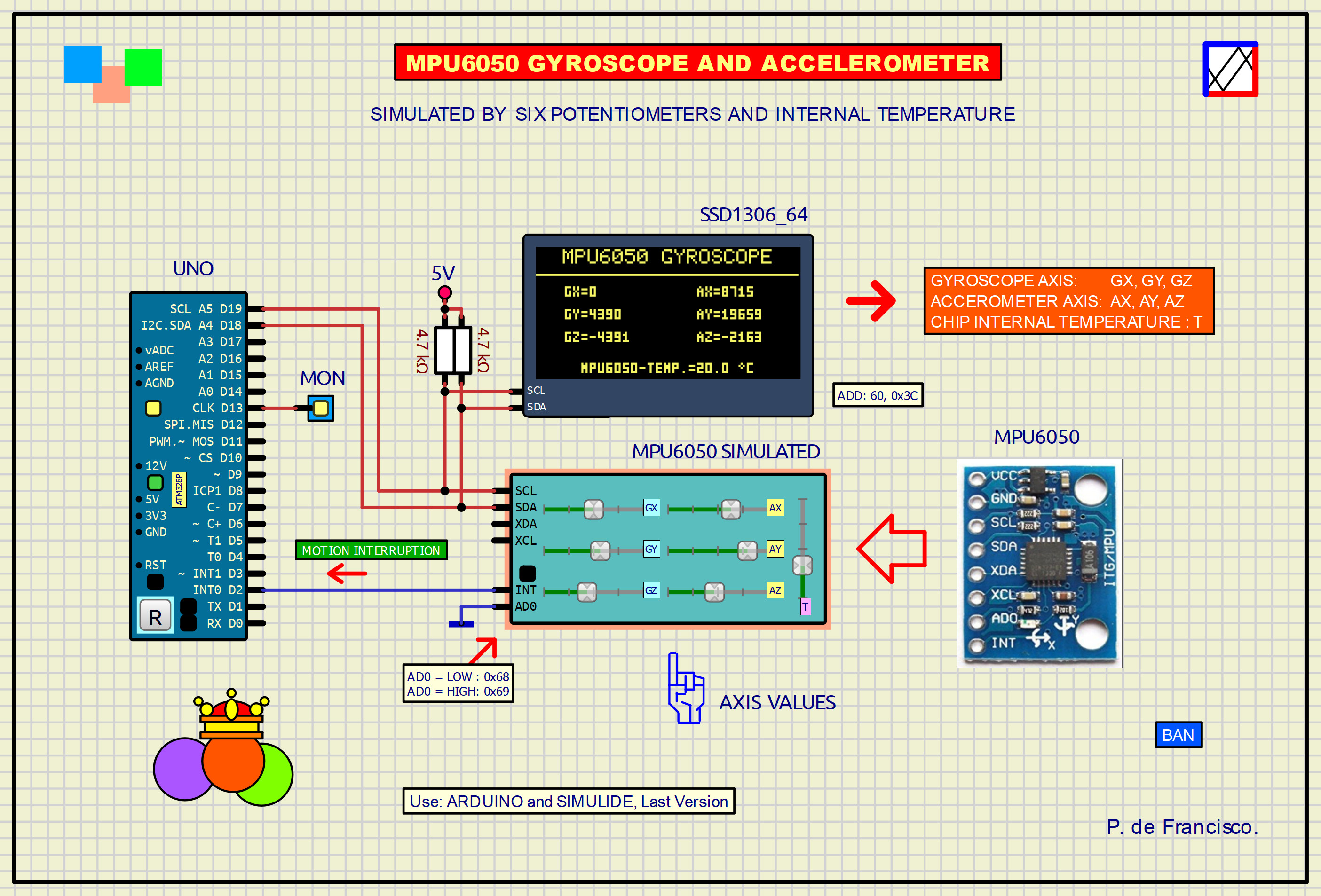
This example consists primarily of a subcircuit with a script program and seven potentiometers to simulate the corresponding axes and the chip's internal temperature. It communicates with the MCU via I2C protocol using ADDRESS 0x68 or 0x69, depending on the INT pin connection. The data is displayed on the OLED with values ranging from -32767 to +32767, with a center zero. These values are obtained by varying the potentiometers from 0 to 5V, converted to 14 bits by the simulated ADC. It is designed for the latest versions of Simulide 1 and 2.
SCRIPT AND INO PROGRAM:
Both are shown separately below.
// MPU2650S - DEFRAN26
// PRUEBA I2C: AX AY AZ TEMP GX GY GZ (0x3B A 0x48)
// TEMP: 0 V = -20.0 C, 5 V = +100.0 C; registro en decimas de grado
// Incluye escrituras simples y lectura secuencial con ACK del maestro.
// INT: interrupcion MOTION enclavada por cambios en los 6 ejes.
// XDA: HIGH cuando el MPU mantiene SDA bajo para enviar ACK.
// MOTION se comprueba al tomar cada muestra de 14 bytes por I2C.

IoPin@ SCL  = component.getPin("SCL");
IoPin@ SDA  = component.getPin("SDA");
IoPin@ AD0  = component.getPin("AD0");
IoPin@ INTP = component.getPin("INT");
IoPin@ XDA  = component.getPin("XDA");
IoPin@ AX   = component.getPin("AX");
IoPin@ AY   = component.getPin("AY");
IoPin@ AZ   = component.getPin("AZ");
IoPin@ GX   = component.getPin("GX");
IoPin@ GY   = component.getPin("GY");
IoPin@ GZ   = component.getPin("GZ");
IoPin@ TEMP = component.getPin("TEMP");
const int ESPERA     = 0;
const int RECIBIR    = 1;
const int ACK_ESCLAVO = 2;
const int TRANSMITIR = 3;
const int ACK_MASTER = 4;
const int FIN        = 5;
int fase = ESPERA;
int bits = 0;
uint recibido = 0;
uint puntero = 0;
uint txDato = 0;
int txBit = 7;
bool primerDato = true;
bool direccionCorrecta = false;
bool direccionLectura = false;
bool novenoAlto = false;
bool oldSCL = true;
bool oldSDA = true;
bool procesando = false;
bool sdaForzada = false;
bool iniciarTxTrasAck = false;
bool siguienteEsValor = false;
bool masterConfirmo = false;
array<uint> registros(128, 0);
// Deteccion MOTION: el umbral MOT_THR se expresa en pasos de 128 cuentas.
// Se compara cada muestra con la inmediatamente anterior; TEMP no interviene.
array<int> muestraAnterior(6, 0);
bool muestraInicializada = false;

void liberarSDA()
{
    sdaForzada = false;
    SDA.setStateZ(true);
}

void bajarSDA()
{
    sdaForzada = true;
    SDA.setOutState(false);
    SDA.setStateZ(false);
}

int convertir16(double v)
{
    if (v < 0.0) v = 0.0;
    if (v > 5.0) v = 5.0;
    int n = int((v / 5.0) * 65535.0 - 32768.0);
    if (n < -32768) n = -32768;
    if (n > 32767) n = 32767;
    return n;
}

// Temperatura simulada: salida en decimas de grado Celsius.
// 0 V -> -200 (-20.0 C), 5 V -> 1000 (+100.0 C).
int convertirTemperatura(double v)
{
    if (v < 0.0) v = 0.0;
    if (v > 5.0) v = 5.0;
    double t10 = v * 240.0 - 200.0;
    return int(t10 >= 0.0 ? t10 + 0.5 : t10 - 0.5);
}

void guardar16(uint dir, int valor)
{
    uint n = uint(valor) & 0xFFFF;
    registros[dir] = (n >> 8) & 0xFF;
    registros[dir + 1] = n & 0xFF;
}

void actualizarSensores()
{
    // PWR_MGMT_1 bit SLEEP: no actualizar mientras duerme.
    if ((registros[0x6B] & 0x40) != 0) return;

    array<int> muestra(6, 0);
    muestra[0] = convertir16(AX.getVoltage());
    muestra[1] = convertir16(AY.getVoltage());
    muestra[2] = convertir16(AZ.getVoltage());
    muestra[3] = convertir16(GX.getVoltage());
    muestra[4] = convertir16(GY.getVoltage());
    muestra[5] = convertir16(GZ.getVoltage());

    // El primer conjunto establece la referencia sin provocar interrupcion.
    if (muestraInicializada && (registros[0x38] & 0x40) != 0)
    {
        int umbral = int(registros[0x1F]) * 128;
        if (umbral < 1) umbral = 1;
        bool movimiento = false;
        for (uint i = 0; i < 6; i++)
        {
            int diferencia = muestra[i] - muestraAnterior[i];
            if (diferencia < 0) diferencia = -diferencia;
            if (diferencia >= umbral) movimiento = true;
        }
        if (movimiento)
        {
            registros[0x3A] |= 0x40; // MOT_INT
            INTP.setOutState(true); // Enclavada hasta leer INT_STATUS
        }
    }
    for (uint i = 0; i < 6; i++) muestraAnterior[i] = muestra[i];
    muestraInicializada = true;

    guardar16(0x3B, muestra[0]);
    guardar16(0x3D, muestra[1]);
    guardar16(0x3F, muestra[2]);
    guardar16(0x41, convertirTemperatura(TEMP.getVoltage()));
    guardar16(0x43, muestra[3]);
    guardar16(0x45, muestra[4]);
    guardar16(0x47, muestra[5]);
}

uint leerRegistro(uint direccion)
{
    direccion &= 0x7F;
    if (direccion == 0x75) return 0x68;
    uint valor = registros[direccion];
    if (direccion == 0x3A)
    {
        registros[0x3A] = 0;
        INTP.setOutState(false);
    }
    return valor;
}

void escribirRegistro(uint direccion, uint valor)
{
    direccion &= 0x7F;
    if (direccion == 0x75) return;
    if (direccion >= 0x3B && direccion <= 0x48) return;
    registros[direccion] = valor & 0xFF;
    if (direccion == 0x38 && (valor & 0x40) == 0)
    {
        registros[0x3A] &= 0xBF;
        INTP.setOutState(false);
    }
    if (direccion == 0x6B && (valor & 0x80) != 0)
    {
        registros[0x6B] = 0x40;
    }
}

void ponerBitTx()
{
    bool uno = ((txDato >> txBit) & 1) != 0;
    if (uno) liberarSDA();
    else bajarSDA();
}

void comenzarTx()
{
    // Captura coherente al comenzar una lectura de los 14 bytes.
    if (puntero == 0x3B) actualizarSensores();
    txDato = leerRegistro(puntero);
    txBit = 7;
    bits = 0;
    fase = TRANSMITIR;
    ponerBitTx(); // SCL esta LOW tras terminar ACK de direccion.
}

void reposo()
{
    fase = ESPERA;
    bits = 0;
    recibido = 0;
    novenoAlto = false;
    XDA.setOutState(false);
    liberarSDA();
}

void comenzar()
{
    // Conserva puntero para START repetido.
    fase = RECIBIR;
    bits = 0;
    recibido = 0;
    direccionCorrecta = false;
    direccionLectura = false;
    primerDato = true;
    siguienteEsValor = false;
    iniciarTxTrasAck = false;
    novenoAlto = false;
    XDA.setOutState(false);
    liberarSDA();
}

void procesarByte(uint valor)
{
    if (primerDato)
    {
        uint esperada = AD0.getInpState() ? 0x69 : 0x68;
        direccionCorrecta = ((valor >> 1) == esperada);
        direccionLectura = ((valor & 1) != 0);
        iniciarTxTrasAck = direccionCorrecta && direccionLectura;
        primerDato = false;
    }
    else
    {
        // Primer byte de datos: puntero; siguientes bytes: valor(es).
        if (!siguienteEsValor)
        {
            puntero = valor & 0x7F;
            siguienteEsValor = true;
            if (puntero >= 0x3B && puntero <= 0x48)
                actualizarSensores();
        }
        else
        {
            escribirRegistro(puntero, valor);
            puntero = (puntero + 1) & 0x7F;
        }
        direccionCorrecta = true;
        iniciarTxTrasAck = false;
    }
}

void setup()
{
}

void reset()
{
    SCL.setPinMode(1);
    AD0.setPinMode(1);
    AX.setPinMode(1);
    AY.setPinMode(1);
    AZ.setPinMode(1);
    GX.setPinMode(1);
    GY.setPinMode(1);
    GZ.setPinMode(1);
    TEMP.setPinMode(1);
    SDA.setPinMode(3);
    SDA.setOutHighV(5.0);
    SDA.setOutState(false);
    SDA.setStateZ(true);

    INTP.setPinMode(3);
    INTP.setOutHighV(3.3);
    INTP.setOutState(false);
    XDA.setPinMode(3);
    XDA.setOutHighV(3.3);
    XDA.setOutState(false);

    procesando = false;
    sdaForzada = false;
    for (uint i = 0; i < 128; i++) registros[i] = 0;
    registros[0x6B] = 0x40; // Estado inicial: dormido
    registros[0x75] = 0x68;
    registros[0x1F] = 8; // MOT_THR por defecto: 1024 cuentas
    registros[0x38] = 0; // INT_ENABLE
    registros[0x3A] = 0; // INT_STATUS
    muestraInicializada = false;
    puntero = 0;
    primerDato = true;
    siguienteEsValor = false;
    iniciarTxTrasAck = false;
    masterConfirmo = false;
    fase = ESPERA;
    bits = 0;
    recibido = 0;
    direccionCorrecta = false;
    direccionLectura = false;
    novenoAlto = false;
    oldSCL = SCL.getInpState();
    oldSDA = SDA.getInpState();

    SCL.changeCallBack(element, true);
    SDA.changeCallBack(element, true);
}

void voltChanged()
{
    if (procesando) return;
    procesando = true;
    bool scl = SCL.getInpState();
    bool sda = SDA.getInpState();
    bool subidaSCL = !oldSCL && scl;
    bool bajadaSCL = oldSCL && !scl;
    bool bajadaSDA = oldSDA && !sda;
    bool subidaSDA = !oldSDA && sda;
    // Preservar la tecnica que hizo funcionar el ACK.
    oldSCL = scl;
    oldSDA = sda;

    if (!subidaSCL && !bajadaSCL && scl && !sdaForzada)
    {
        if (bajadaSDA) comenzar();
        else if (subidaSDA) reposo();
    }

    if (fase == RECIBIR)
    {
        if (subidaSCL)
        {
                    recibido = ((recibido << 1) | (sda ? 1 : 0)) & 0xFF;
            bits++;
            if (bits == 8) procesarByte(recibido);
        }
        else if (bajadaSCL && bits == 8)
        {
            // Preparar ACK inmediatamente despues del octavo bit.
            if (direccionCorrecta)
            {
                fase = ACK_ESCLAVO;
                novenoAlto = false;
                XDA.setOutState(true);
                bajarSDA();
            }
            else
            {
                fase = FIN;
            }
        }
    }
    else if (fase == ACK_ESCLAVO)
    {
        if (subidaSCL) novenoAlto = true;
        else if (bajadaSCL && novenoAlto)
        {
            novenoAlto = false;
            fase = FIN; // Antes de modificar SDA, igual que ACK probado.
            liberarSDA();
            XDA.setOutState(false);
            if (iniciarTxTrasAck)
            {
                comenzarTx();
            }
            else
            {
                fase = RECIBIR;
                bits = 0;
                recibido = 0;
            }
        }
    }
    else if (fase == TRANSMITIR)
    {
        if (subidaSCL)
        {
            bits++;
        }
        else if (bajadaSCL)
        {
            if (bits == 8)
            {
                // Tras transmitir los 8 bits, liberar para ACK del master.
                liberarSDA();
                fase = ACK_MASTER;
                novenoAlto = false;
            }
            else if (bits > 0 && bits < 8)
            {
                txBit = 7 - bits;
                ponerBitTx();
            }
        }
    }
    else if (fase == ACK_MASTER)
    {
        if (subidaSCL)
        {
            novenoAlto = true;
            masterConfirmo = !sda; // ACK: LOW; NACK: HIGH
        }
        else if (bajadaSCL && novenoAlto)
        {
            fase = FIN;
            if (masterConfirmo)
            {
                puntero = (puntero + 1) & 0x7F;
                comenzarTx(); // SCL ya esta en LOW
            }
            else
            {
                liberarSDA();
            }
        }
    }

    // No actualizar oldSCL/oldSDA a partir de las salidas propias.
    procesando = false;
}
// MPU6050 GYROSCOPE & ACCELOEROMETER. DEFRAN26A // Lectura de 14 bytes: AX AY AZ TEMP GX GY GZ. // INT MOTION del MPU6050 conectado al pin D2 del UNO. // Temperatura en decimas de grado (-20.0 a 100.0 C). #include <Wire.h> #include <Adafruit_GFX.h> #include <Adafruit_SSD1306.h> #include <avr/pgmspace.h> #define ANCHO 128 #define ALTO 64 #define OLED_RESET -1 #define DIR_OLED 0x3C #define DIR_MPU 0x68 Adafruit_SSD1306 oled(ANCHO, ALTO, &Wire, OLED_RESET); int16_t dato[7]; // AX AY AZ TEMP GX GY GZ int16_t anterior[7]; bool primera = true; const byte PIN_INT_MPU = 2; const byte PIN_ESTADO = 13; // HIGH = OLED e I2C funcionando volatile bool avisoMovimiento = false; uint32_t contadorMotion = 0; bool configuracionOK = false; unsigned long anteriorLectura = 0; const char letras[] PROGMEM = "0123456789-+=. ACEGMPTXYZU~"; // Caracteres (3x5 pixeles) const uint8_t fuente[][5] PROGMEM = // Cada fila tres bits: 100=izquierda, 010=centro, 001=derecha { {7,5,5,5,7}, // 0 {2,6,2,2,7}, // 1 {7,1,7,4,7}, // 2 {7,1,7,1,7}, // 3 {5,5,7,1,1}, // 4 {7,4,7,1,7}, // 5 {7,4,7,5,7}, // 6 {7,1,1,1,1}, // 7 {7,5,7,5,7}, // 8 {7,5,7,1,7}, // 9 {0,0,7,0,0}, // - {0,2,7,2,0}, // + {0,7,0,7,0}, // = {0,0,0,0,2}, // . {0,0,0,0,0}, // espacio {2,5,7,5,5}, // A {7,4,4,4,7}, // C {7,4,7,4,7}, // E {7,4,5,5,7}, // G {5,7,7,5,5}, // M {7,5,7,4,4}, // P {7,2,2,2,2}, // T {5,5,2,5,5}, // X {5,5,2,2,2}, // Y {7,1,2,4,7}, // Z {5,5,5,5,7}, // U {2,5,2,0,0} // ~ = simbolo de grados }; void setup() { pinMode(PIN_ESTADO, OUTPUT); digitalWrite(PIN_ESTADO, LOW); Wire.begin(); pinMode(PIN_INT_MPU, INPUT); if (!oled.begin(SSD1306_SWITCHCAPVCC, DIR_OLED)) {} oled.clearDisplay(); oled.setTextSize(1); oled.setTextColor(SSD1306_WHITE); oled.setCursor((ANCHO - 17 * 6) / 2, 1); oled.print(F("MPU6050 GYROSCOPE")); oled.drawFastHLine(0, 13, 127, SSD1306_WHITE); for (byte i = 0; i < 7; i++) dato[i] = 0; // Mostrar campos desde el principio, incluso antes de la primera lectura pantallaValores(); oled.display(); bool despertarOK = escribirRegistro(0x6B, 0x00); bool umbralOK = escribirRegistro(0x1F, 8); // Umbral de 1024 cuentas en el simulador: 8 * 128 leerRegistroMPU(0x3A); // Eliminar cualquier evento anterior y habilitar SOLO MOTION (bit 6) attachInterrupt(digitalPinToInterrupt(PIN_INT_MPU), interrupcionMovimiento, RISING); bool motionOK = escribirRegistro(0x38, 0x40); configuracionOK = despertarOK && umbralOK && motionOK; } void loop() { if (millis() - anteriorLectura < 500) return; anteriorLectura = millis(); if (!leerMedidas()) { digitalWrite(PIN_ESTADO, LOW); oled.fillRect(0, 53, 128, 11, SSD1306_BLACK); // Mostrar fallo lectura en LED zona inferior textoCompacto(35, 56, "ERROR I2C"); oled.display(); return; } digitalWrite(PIN_ESTADO, configuracionOK ? HIGH : LOW); // Encender D13 solo si la configuracion y la lectura I2C son correctas bool cambio = true; // Forzar el redibujado, tambien tras un error anterior for (byte i = 0; i < 7; i++) if (dato[i] != anterior[i]) cambio = true; if (cambio) { oled.fillRect(0, 17, 128, 47, SSD1306_BLACK); pantallaValores(); oled.display(); for (byte i = 0; i < 7; i++) anterior[i] = dato[i]; primera = false; } if (avisoMovimiento || digitalRead(PIN_INT_MPU) == HIGH) // La deteccion al tomar muestra sensores. Leer INT_STATUS limpia salida INT si enclavada { int estado = leerRegistroMPU(0x3A); if (estado >= 0 && (estado & 0x40)) {contadorMotion++;} if (estado >= 0) avisoMovimiento = false; } } void interrupcionMovimiento() { avisoMovimiento = true; // Sin operaciones I2C dentro de ISR } void caracterCompacto(int16_t x, int16_t y, char c) { byte indice = 14; // espacio si el caracter no existe for (byte i = 0; i < sizeof(letras) - 1; i++) { if ((char)pgm_read_byte(&letras[i]) == c) { indice = i; break; } } for (byte f=0; f<5; f++) { byte bits = pgm_read_byte(&fuente[indice][f]); for (byte col=0; col<3; col++) if (bits & (4 >> col)) oled.drawPixel(x+col, y+f, SSD1306_WHITE); } } void textoCompacto(int16_t x, int16_t y, const char* s) { while (*s && x <= ANCHO - 3) { caracterCompacto(x, y, *s++); x += 4; // 3 pixeles de caracter + 1 de separacion } } bool escribirRegistro(byte reg, byte valor) { Wire.beginTransmission(DIR_MPU); Wire.write(reg); Wire.write(valor); return Wire.endTransmission() == 0; } int leerRegistroMPU(byte reg) { Wire.beginTransmission(DIR_MPU); Wire.write(reg); if (Wire.endTransmission(false) != 0) return -1; if (Wire.requestFrom((uint8_t)DIR_MPU, (uint8_t)1) != 1) return -1; return Wire.read(); } bool leerMedidas() { Wire.beginTransmission(DIR_MPU); Wire.write(0x3B); if (Wire.endTransmission(false) != 0) return false; if (Wire.requestFrom((uint8_t)DIR_MPU, (uint8_t)14) != 14) return false; for (byte i=0; i<7; i++) { uint16_t hi = Wire.read(); uint16_t lo = Wire.read(); dato[i] = (int16_t)((hi << 8) | lo); } return true; } int16_t xTextoCentrado(const char* s, int16_t inicio, int16_t ancho) { int16_t pixeles = (int16_t)strlen(s) * 4 - 1; return inicio + (ancho - pixeles) / 2; } void pantallaValores() { char linea[28]; const byte y[3] = {19, 30, 41}; // Columna izquierda: giroscopios. Columna derecha: acelerometros. const char* nombresG[3] = {"GX", "GY", "GZ"}; const char* nombresA[3] = {"AX", "AY", "AZ"}; for (byte i = 0; i < 3; i++) { snprintf(linea, sizeof(linea), "%s=%d", nombresG[i], dato[4 + i]); textoCompacto(14, y[i], linea); // X fija: no se mueve con los digitos snprintf(linea, sizeof(linea), "%s=%d", nombresA[i], dato[i]); textoCompacto(78, y[i], linea); // X fija: no se mueve con los digitos } int32_t t = dato[3]; // Temperatura en linea inferior unsigned int magnitud = (unsigned int)(t < 0 ? -t : t); snprintf(linea, sizeof(linea), "MPU6050-TEMP.=%s%u.%u ~C", t < 0 ? "-" : "", magnitud / 10, magnitud % 10); textoCompacto(xTextoCentrado(linea, 0, ANCHO), 56, linea); }FILES INCLUDED:
The ZIP file contains all parts of the example, hardware and software. The subcircuit is included as a separate copy for the user's discretionary use.
P. de Francisco
The MPU6050 is a 6-axis electronic sensor that combines a 3-axis accelerometer and a 3-axis gyroscope onto a single chip. It is widely used in robotics projects, drones, game controllers, and wearable devices to measure an object's orientation, motion, vibrations, and acceleration. Key Features:
• Accelerometer: Measures linear acceleration and gravitational forces along the X, Y, and Z axes. It is used to detect tilt relative to the ground and linear motion.
• Gyroscope: Measures angular velocity (rotation speed) along the same three axes. It is used to accurately track rapid turns.
• Digital Motion Processor (DMP): Features an internal processor that can perform calculations to fuse the accelerometer and gyroscope data, reducing the workload on the main microcontroller. The purpose of the DMP is for the sensor to internally calculate the exact orientation (tilt angles) using mathematical algorithms (quaternions) and provide filtered, ready-to-use pitch, roll, and yaw values. This option is not implemented in the version of this example.
The MPU6050's internal temperature sensor is not primarily intended for measuring ambient temperature, but rather for a crucial technical function: compensating for gyroscope and accelerometer drift caused by heat. The microchip materials (silicon and microscopic mechanical parts, MEMS) expand or contract microscopically when the temperature changes. This causes the gyroscope and accelerometer readings to vary (drift) even when the sensor is completely stationary. By measuring the chip's exact internal temperature, the firmware or the main processor can apply mathematical formulas to correct this error in real time.
EXAMPLE HARDWARE AND SOFTWARE:
This example consists primarily of a subcircuit with a script program and seven potentiometers to simulate the corresponding axes and the chip's internal temperature. It communicates with the MCU via I2C protocol using ADDRESS 0x68 or 0x69, depending on the INT pin connection. The data is displayed on the OLED with values ranging from -32767 to +32767, with a center zero. These values are obtained by varying the potentiometers from 0 to 5V, converted to 14 bits by the simulated ADC. It is designed for the latest versions of Simulide 1 and 2.
SCRIPT AND INO PROGRAM:
Both are shown separately below.
// MPU2650S - DEFRAN26
// PRUEBA I2C: AX AY AZ TEMP GX GY GZ (0x3B A 0x48)
// TEMP: 0 V = -20.0 C, 5 V = +100.0 C; registro en decimas de grado
// Incluye escrituras simples y lectura secuencial con ACK del maestro.
// INT: interrupcion MOTION enclavada por cambios en los 6 ejes.
// XDA: HIGH cuando el MPU mantiene SDA bajo para enviar ACK.
// MOTION se comprueba al tomar cada muestra de 14 bytes por I2C.
IoPin@ SCL = component.getPin("SCL");
IoPin@ SDA = component.getPin("SDA");
IoPin@ AD0 = component.getPin("AD0");
IoPin@ INTP = component.getPin("INT");
IoPin@ XDA = component.getPin("XDA");
IoPin@ AX = component.getPin("AX");
IoPin@ AY = component.getPin("AY");
IoPin@ AZ = component.getPin("AZ");
IoPin@ GX = component.getPin("GX");
IoPin@ GY = component.getPin("GY");
IoPin@ GZ = component.getPin("GZ");
IoPin@ TEMP = component.getPin("TEMP");
const int ESPERA = 0;
const int RECIBIR = 1;
const int ACK_ESCLAVO = 2;
const int TRANSMITIR = 3;
const int ACK_MASTER = 4;
const int FIN = 5;
int fase = ESPERA;
int bits = 0;
uint recibido = 0;
uint puntero = 0;
uint txDato = 0;
int txBit = 7;
bool primerDato = true;
bool direccionCorrecta = false;
bool direccionLectura = false;
bool novenoAlto = false;
bool oldSCL = true;
bool oldSDA = true;
bool procesando = false;
bool sdaForzada = false;
bool iniciarTxTrasAck = false;
bool siguienteEsValor = false;
bool masterConfirmo = false;
array<uint> registros(128, 0);
// Deteccion MOTION: el umbral MOT_THR se expresa en pasos de 128 cuentas.
// Se compara cada muestra con la inmediatamente anterior; TEMP no interviene.
array<int> muestraAnterior(6, 0);
bool muestraInicializada = false;
void liberarSDA()
{
sdaForzada = false;
SDA.setStateZ(true);
}
void bajarSDA()
{
sdaForzada = true;
SDA.setOutState(false);
SDA.setStateZ(false);
}
int convertir16(double v)
{
if (v < 0.0) v = 0.0;
if (v > 5.0) v = 5.0;
int n = int((v / 5.0) * 65535.0 - 32768.0);
if (n < -32768) n = -32768;
if (n > 32767) n = 32767;
return n;
}
// Temperatura simulada: salida en decimas de grado Celsius.
// 0 V -> -200 (-20.0 C), 5 V -> 1000 (+100.0 C).
int convertirTemperatura(double v)
{
if (v < 0.0) v = 0.0;
if (v > 5.0) v = 5.0;
double t10 = v * 240.0 - 200.0;
return int(t10 >= 0.0 ? t10 + 0.5 : t10 - 0.5);
}
void guardar16(uint dir, int valor)
{
uint n = uint(valor) & 0xFFFF;
registros[dir] = (n >> 8) & 0xFF;
registros[dir + 1] = n & 0xFF;
}
void actualizarSensores()
{
// PWR_MGMT_1 bit SLEEP: no actualizar mientras duerme.
if ((registros[0x6B] & 0x40) != 0) return;
array<int> muestra(6, 0);
muestra[0] = convertir16(AX.getVoltage());
muestra[1] = convertir16(AY.getVoltage());
muestra[2] = convertir16(AZ.getVoltage());
muestra[3] = convertir16(GX.getVoltage());
muestra[4] = convertir16(GY.getVoltage());
muestra[5] = convertir16(GZ.getVoltage());
// El primer conjunto establece la referencia sin provocar interrupcion.
if (muestraInicializada && (registros[0x38] & 0x40) != 0)
{
int umbral = int(registros[0x1F]) * 128;
if (umbral < 1) umbral = 1;
bool movimiento = false;
for (uint i = 0; i < 6; i++)
{
int diferencia = muestra[i] - muestraAnterior[i];
if (diferencia < 0) diferencia = -diferencia;
if (diferencia >= umbral) movimiento = true;
}
if (movimiento)
{
registros[0x3A] |= 0x40; // MOT_INT
INTP.setOutState(true); // Enclavada hasta leer INT_STATUS
}
}
for (uint i = 0; i < 6; i++) muestraAnterior[i] = muestra[i];
muestraInicializada = true;
guardar16(0x3B, muestra[0]);
guardar16(0x3D, muestra[1]);
guardar16(0x3F, muestra[2]);
guardar16(0x41, convertirTemperatura(TEMP.getVoltage()));
guardar16(0x43, muestra[3]);
guardar16(0x45, muestra[4]);
guardar16(0x47, muestra[5]);
}
uint leerRegistro(uint direccion)
{
direccion &= 0x7F;
if (direccion == 0x75) return 0x68;
uint valor = registros[direccion];
if (direccion == 0x3A)
{
registros[0x3A] = 0;
INTP.setOutState(false);
}
return valor;
}
void escribirRegistro(uint direccion, uint valor)
{
direccion &= 0x7F;
if (direccion == 0x75) return;
if (direccion >= 0x3B && direccion <= 0x48) return;
registros[direccion] = valor & 0xFF;
if (direccion == 0x38 && (valor & 0x40) == 0)
{
registros[0x3A] &= 0xBF;
INTP.setOutState(false);
}
if (direccion == 0x6B && (valor & 0x80) != 0)
{
registros[0x6B] = 0x40;
}
}
void ponerBitTx()
{
bool uno = ((txDato >> txBit) & 1) != 0;
if (uno) liberarSDA();
else bajarSDA();
}
void comenzarTx()
{
// Captura coherente al comenzar una lectura de los 14 bytes.
if (puntero == 0x3B) actualizarSensores();
txDato = leerRegistro(puntero);
txBit = 7;
bits = 0;
fase = TRANSMITIR;
ponerBitTx(); // SCL esta LOW tras terminar ACK de direccion.
}
void reposo()
{
fase = ESPERA;
bits = 0;
recibido = 0;
novenoAlto = false;
XDA.setOutState(false);
liberarSDA();
}
void comenzar()
{
// Conserva puntero para START repetido.
fase = RECIBIR;
bits = 0;
recibido = 0;
direccionCorrecta = false;
direccionLectura = false;
primerDato = true;
siguienteEsValor = false;
iniciarTxTrasAck = false;
novenoAlto = false;
XDA.setOutState(false);
liberarSDA();
}
void procesarByte(uint valor)
{
if (primerDato)
{
uint esperada = AD0.getInpState() ? 0x69 : 0x68;
direccionCorrecta = ((valor >> 1) == esperada);
direccionLectura = ((valor & 1) != 0);
iniciarTxTrasAck = direccionCorrecta && direccionLectura;
primerDato = false;
}
else
{
// Primer byte de datos: puntero; siguientes bytes: valor(es).
if (!siguienteEsValor)
{
puntero = valor & 0x7F;
siguienteEsValor = true;
if (puntero >= 0x3B && puntero <= 0x48)
actualizarSensores();
}
else
{
escribirRegistro(puntero, valor);
puntero = (puntero + 1) & 0x7F;
}
direccionCorrecta = true;
iniciarTxTrasAck = false;
}
}
void setup()
{
}
void reset()
{
SCL.setPinMode(1);
AD0.setPinMode(1);
AX.setPinMode(1);
AY.setPinMode(1);
AZ.setPinMode(1);
GX.setPinMode(1);
GY.setPinMode(1);
GZ.setPinMode(1);
TEMP.setPinMode(1);
SDA.setPinMode(3);
SDA.setOutHighV(5.0);
SDA.setOutState(false);
SDA.setStateZ(true);
INTP.setPinMode(3);
INTP.setOutHighV(3.3);
INTP.setOutState(false);
XDA.setPinMode(3);
XDA.setOutHighV(3.3);
XDA.setOutState(false);
procesando = false;
sdaForzada = false;
for (uint i = 0; i < 128; i++) registros[i] = 0;
registros[0x6B] = 0x40; // Estado inicial: dormido
registros[0x75] = 0x68;
registros[0x1F] = 8; // MOT_THR por defecto: 1024 cuentas
registros[0x38] = 0; // INT_ENABLE
registros[0x3A] = 0; // INT_STATUS
muestraInicializada = false;
puntero = 0;
primerDato = true;
siguienteEsValor = false;
iniciarTxTrasAck = false;
masterConfirmo = false;
fase = ESPERA;
bits = 0;
recibido = 0;
direccionCorrecta = false;
direccionLectura = false;
novenoAlto = false;
oldSCL = SCL.getInpState();
oldSDA = SDA.getInpState();
SCL.changeCallBack(element, true);
SDA.changeCallBack(element, true);
}
void voltChanged()
{
if (procesando) return;
procesando = true;
bool scl = SCL.getInpState();
bool sda = SDA.getInpState();
bool subidaSCL = !oldSCL && scl;
bool bajadaSCL = oldSCL && !scl;
bool bajadaSDA = oldSDA && !sda;
bool subidaSDA = !oldSDA && sda;
// Preservar la tecnica que hizo funcionar el ACK.
oldSCL = scl;
oldSDA = sda;
if (!subidaSCL && !bajadaSCL && scl && !sdaForzada)
{
if (bajadaSDA) comenzar();
else if (subidaSDA) reposo();
}
if (fase == RECIBIR)
{
if (subidaSCL)
{
recibido = ((recibido << 1) | (sda ? 1 : 0)) & 0xFF;
bits++;
if (bits == 8) procesarByte(recibido);
}
else if (bajadaSCL && bits == 8)
{
// Preparar ACK inmediatamente despues del octavo bit.
if (direccionCorrecta)
{
fase = ACK_ESCLAVO;
novenoAlto = false;
XDA.setOutState(true);
bajarSDA();
}
else
{
fase = FIN;
}
}
}
else if (fase == ACK_ESCLAVO)
{
if (subidaSCL) novenoAlto = true;
else if (bajadaSCL && novenoAlto)
{
novenoAlto = false;
fase = FIN; // Antes de modificar SDA, igual que ACK probado.
liberarSDA();
XDA.setOutState(false);
if (iniciarTxTrasAck)
{
comenzarTx();
}
else
{
fase = RECIBIR;
bits = 0;
recibido = 0;
}
}
}
else if (fase == TRANSMITIR)
{
if (subidaSCL)
{
bits++;
}
else if (bajadaSCL)
{
if (bits == 8)
{
// Tras transmitir los 8 bits, liberar para ACK del master.
liberarSDA();
fase = ACK_MASTER;
novenoAlto = false;
}
else if (bits > 0 && bits < 8)
{
txBit = 7 - bits;
ponerBitTx();
}
}
}
else if (fase == ACK_MASTER)
{
if (subidaSCL)
{
novenoAlto = true;
masterConfirmo = !sda; // ACK: LOW; NACK: HIGH
}
else if (bajadaSCL && novenoAlto)
{
fase = FIN;
if (masterConfirmo)
{
puntero = (puntero + 1) & 0x7F;
comenzarTx(); // SCL ya esta en LOW
}
else
{
liberarSDA();
}
}
}
// No actualizar oldSCL/oldSDA a partir de las salidas propias.
procesando = false;
}
// MPU6050 GYROSCOPE & ACCELOEROMETER.  DEFRAN26A
// Lectura de 14 bytes: AX AY AZ TEMP GX GY GZ.
// INT MOTION del MPU6050 conectado al pin D2 del UNO.
// Temperatura en decimas de grado (-20.0 a 100.0 C).

#include <Wire.h>
#include <Adafruit_GFX.h>
#include <Adafruit_SSD1306.h>
#include <avr/pgmspace.h>
#define ANCHO 128
#define ALTO 64
#define OLED_RESET -1
#define DIR_OLED 0x3C
#define DIR_MPU  0x68
Adafruit_SSD1306 oled(ANCHO, ALTO, &Wire, OLED_RESET);
int16_t dato[7];       // AX AY AZ TEMP GX GY GZ
int16_t anterior[7];
bool primera = true;
const byte PIN_INT_MPU = 2;
const byte PIN_ESTADO = 13;  // HIGH = OLED e I2C funcionando
volatile bool avisoMovimiento = false;
uint32_t contadorMotion = 0;
bool configuracionOK = false;
unsigned long anteriorLectura = 0;
const char letras[] PROGMEM = "0123456789-+=. ACEGMPTXYZU~";  // Caracteres (3x5 pixeles)
const uint8_t fuente[][5] PROGMEM =  // Cada fila tres bits: 100=izquierda, 010=centro, 001=derecha
{
  {7,5,5,5,7}, // 0
  {2,6,2,2,7}, // 1
  {7,1,7,4,7}, // 2
  {7,1,7,1,7}, // 3
  {5,5,7,1,1}, // 4
  {7,4,7,1,7}, // 5
  {7,4,7,5,7}, // 6
  {7,1,1,1,1}, // 7
  {7,5,7,5,7}, // 8
  {7,5,7,1,7}, // 9
  {0,0,7,0,0}, // -
  {0,2,7,2,0}, // +
  {0,7,0,7,0}, // =
  {0,0,0,0,2}, // .
  {0,0,0,0,0}, // espacio
  {2,5,7,5,5}, // A
  {7,4,4,4,7}, // C
  {7,4,7,4,7}, // E
  {7,4,5,5,7}, // G
  {5,7,7,5,5}, // M
  {7,5,7,4,4}, // P
  {7,2,2,2,2}, // T
  {5,5,2,5,5}, // X
  {5,5,2,2,2}, // Y
  {7,1,2,4,7}, // Z
  {5,5,5,5,7}, // U
  {2,5,2,0,0}  // ~ = simbolo de grados
};

void setup()
{
  pinMode(PIN_ESTADO, OUTPUT);
  digitalWrite(PIN_ESTADO, LOW);
  Wire.begin();
  pinMode(PIN_INT_MPU, INPUT);
  if (!oled.begin(SSD1306_SWITCHCAPVCC, DIR_OLED)) {}
  oled.clearDisplay();
  oled.setTextSize(1);
  oled.setTextColor(SSD1306_WHITE);
  oled.setCursor((ANCHO - 17 * 6) / 2, 1);
  oled.print(F("MPU6050 GYROSCOPE"));
  oled.drawFastHLine(0, 13, 127, SSD1306_WHITE);
  for (byte i = 0; i < 7; i++) dato[i] = 0;  // Mostrar campos desde el principio, incluso antes de la primera lectura
  pantallaValores();
  oled.display();
  bool despertarOK = escribirRegistro(0x6B, 0x00);
  bool umbralOK = escribirRegistro(0x1F, 8);  // Umbral de 1024 cuentas en el simulador: 8 * 128
  leerRegistroMPU(0x3A);  // Eliminar cualquier evento anterior y habilitar SOLO MOTION (bit 6)
  attachInterrupt(digitalPinToInterrupt(PIN_INT_MPU), interrupcionMovimiento, RISING);
  bool motionOK = escribirRegistro(0x38, 0x40);
  configuracionOK = despertarOK && umbralOK && motionOK;
}

void loop()
{
  if (millis() - anteriorLectura < 500) return;
  anteriorLectura = millis();
  if (!leerMedidas())
  {
    digitalWrite(PIN_ESTADO, LOW);
    oled.fillRect(0, 53, 128, 11, SSD1306_BLACK);  // Mostrar fallo lectura en LED zona inferior
    textoCompacto(35, 56, "ERROR I2C");
    oled.display();
    return;
  }
  digitalWrite(PIN_ESTADO, configuracionOK ? HIGH : LOW);  // Encender D13 solo si la configuracion y la lectura I2C son correctas
  bool cambio = true;  // Forzar el redibujado, tambien tras un error anterior
  for (byte i = 0; i < 7; i++)
    if (dato[i] != anterior[i]) cambio = true;
  if (cambio)
  {
    oled.fillRect(0, 17, 128, 47, SSD1306_BLACK);
    pantallaValores();
    oled.display();
    for (byte i = 0; i < 7; i++) anterior[i] = dato[i];
    primera = false;
  }
  if (avisoMovimiento || digitalRead(PIN_INT_MPU) == HIGH)  // La deteccion al tomar muestra sensores. Leer INT_STATUS limpia salida INT si enclavada
  {
    int estado = leerRegistroMPU(0x3A);
    if (estado >= 0 && (estado & 0x40)) {contadorMotion++;}
    if (estado >= 0) avisoMovimiento = false;
  }
}

void interrupcionMovimiento()
{
  avisoMovimiento = true;  // Sin operaciones I2C dentro de ISR
}

void caracterCompacto(int16_t x, int16_t y, char c)
{
  byte indice = 14;  // espacio si el caracter no existe
  for (byte i = 0; i < sizeof(letras) - 1; i++)
  {
    if ((char)pgm_read_byte(&letras[i]) == c) { indice = i; break; }
  }
  for (byte f=0; f<5; f++)
  {
    byte bits = pgm_read_byte(&fuente[indice][f]);
    for (byte col=0; col<3; col++) if (bits & (4 >> col)) oled.drawPixel(x+col, y+f, SSD1306_WHITE);
  }
}

void textoCompacto(int16_t x, int16_t y, const char* s)
{
  while (*s && x <= ANCHO - 3)
  {
    caracterCompacto(x, y, *s++);
    x += 4;  // 3 pixeles de caracter + 1 de separacion
  }
}

bool escribirRegistro(byte reg, byte valor)
{
  Wire.beginTransmission(DIR_MPU);
  Wire.write(reg);
  Wire.write(valor);
  return Wire.endTransmission() == 0;
}

int leerRegistroMPU(byte reg)
{
  Wire.beginTransmission(DIR_MPU);
  Wire.write(reg);
  if (Wire.endTransmission(false) != 0) return -1;
  if (Wire.requestFrom((uint8_t)DIR_MPU, (uint8_t)1) != 1) return -1;
  return Wire.read();
}

bool leerMedidas()
{
  Wire.beginTransmission(DIR_MPU);
  Wire.write(0x3B);
  if (Wire.endTransmission(false) != 0) return false;
  if (Wire.requestFrom((uint8_t)DIR_MPU, (uint8_t)14) != 14) return false;
  for (byte i=0; i<7; i++)
  {
    uint16_t hi = Wire.read();
    uint16_t lo = Wire.read();
    dato[i] = (int16_t)((hi << 8) | lo);
  }
  return true;
}

int16_t xTextoCentrado(const char* s, int16_t inicio, int16_t ancho)
{
  int16_t pixeles = (int16_t)strlen(s) * 4 - 1;
  return inicio + (ancho - pixeles) / 2;
}

void pantallaValores()
{
  char linea[28];
  const byte y[3] = {19, 30, 41};  // Columna izquierda: giroscopios. Columna derecha: acelerometros.
  const char* nombresG[3] = {"GX", "GY", "GZ"};
  const char* nombresA[3] = {"AX", "AY", "AZ"};
  for (byte i = 0; i < 3; i++)
  {
    snprintf(linea, sizeof(linea), "%s=%d", nombresG[i], dato[4 + i]);
    textoCompacto(14, y[i], linea); // X fija: no se mueve con los digitos
    snprintf(linea, sizeof(linea), "%s=%d", nombresA[i], dato[i]);
    textoCompacto(78, y[i], linea);  // X fija: no se mueve con los digitos
  }
  int32_t t = dato[3];   // Temperatura en linea inferior
  unsigned int magnitud = (unsigned int)(t < 0 ? -t : t);
  snprintf(linea, sizeof(linea), "MPU6050-TEMP.=%s%u.%u ~C", t < 0 ? "-" : "", magnitud / 10, magnitud % 10);
  textoCompacto(xTextoCentrado(linea, 0, ANCHO), 56, linea);
}
FILES INCLUDED:
The ZIP file contains all parts of the example, hardware and software. The subcircuit is included as a separate copy for the user's discretionary use.
P. de Francisco
Uploaded files: