
369_TRIODE THERMOIONIC VALVE

Quote from Defran on September 16, 2026, 12:47 pm
The thermionic valve is the predecessor to the transistor; it marked the beginning of the world of electronics. Since its invention by Lee de Forest (1873–1961) in 1906, it has been a highly successful component in audio amplification, long-distance telephony, radio and television transmission and reception, industrial applications, and even the early stages of computing.
Operating within an absolute vacuum inside the valve, it functions based on the emission of electrons from an incandescent filament; these electrons are attracted to the plate, which must always maintain a positive bias. The filament is enclosed by a metal cylinder known as the cathode, which—being connected to the filament—regulates the flow of electrons. Situated between the cathode and the plate is the grid, a perforated cylinder that controls the electron flow toward the plate, thereby generating signal gain at the plate.
The subcircuit proposed here was created by first writing a script and subsequently adapting it to add a graphical layer. Below, we present the commented text of the "as" script (AngelScript).
// TRIODE THERMOIONIC VALVE. DEFRAN26

IoPin@ H=component.getPin("H");  // Filamento +3.3 V
IoPin@ K=component.getPin("K");  // Catodo + extremo filamento
IoPin@ G=component.getPin("G");  // Rejilla
IoPin@ P=component.getPin("P");  // Placa
double ganancia = 20.0;
double kTriodo=0.00020;  // Constante de corriente del triodo.
double R_OFF = 1000000000.0;  // Limites...
double R_MIN = 100.0;
double I_MAX = 0.050;
bool actualizando = false;

void setup()
{
  print("Triodo inicializado");
}

void reset()
{
  H.setPinMode(1);
  K.setPinMode(1);
  G.setPinMode(1);
  P.setPinMode(3);  // La placa, Salida con impedancia variable hacia el catodo
  H.changeCallBack(element, true);
  K.changeCallBack(element, true);
  G.changeCallBack(element, true);
  P.changeCallBack(element, true);
  actualizarTriodo();
}

void voltChanged()
{
  actualizarTriodo();
}

void setGanancia(double val)  // PROPIEDAD GANANCIA
{
  if (val < 2.0)  val = 2.0;
  if (val > 200.0) val = 200.0;
  ganancia = val;
  actualizarTriodo();
}

double getGanancia()
{
  return ganancia;
}

void actualizarTriodo()  // MODELO DEL TRIODO
{
  if (actualizando) return;
  actualizando = true;
  double vh  = H.getVoltage();
  double vk  = K.getVoltage();
  double vg  = G.getVoltage();
  double vp  = P.getVoltage();
  double vf = vh - vk;   // TENSION DEL FILAMENTO
  if (vf < 0.0) vf = -vf;
  double calor = 0.0;  // FACTOR DE CALENTAMIENTO
  if (vf <= 2.0) {calor = 0.0;}
  else if (vf >= 3.3) {calor = 1.0;}
  else {calor = (vf - 2.0) / 1.3;}
  double vgk = vg - vk;  // TENSIONES REFERIDAS AL CATODO
  double vpk = vp - vk;
  if ((calor <= 0.0) || (vpk <= 0.0))  // VALVULA APAGADA
  {
     P.setVoltage(vk);
     P.setImpedance(R_OFF);
     actualizando = false;
     return;
  }
  // ECUACION SIMPLIFICADA DEL TRIODO: Vef Vgk+Vpk/mu, mu=ganancia
  double vef = vgk + vpk / ganancia;
  if (vef <= 0.0)  // CORTE
  {
    P.setVoltage(vk);
    P.setImpedance(R_OFF);
    actualizando = false;
    return;
  }
  // CORRIENTE DE PLACA. Aproximacion cuadratica: Ia = K * Vef^2
  double ia = kTriodo * vef * vef;
  ia = ia * calor;
  if (ia > I_MAX) {ia = I_MAX;}  // LIMITAR CORRIENTE MAXIMA
  // CONVERTIR Ia EN RESISTENCIA DINAMICA: R = Vpk / Ia
  double rp;
  if (ia < 0.000001) {rp = R_OFF;}
  else {rp = vpk / ia;}
  if (rp < R_MIN) {rp = R_MIN;}
  if (rp > R_OFF) {rp = R_OFF;}
  P.setVoltage(vk);  // La placa conduce hacia el catodo
  P.setImpedance(rp);
  actualizando = false;
}
All necessary files are packaged in a ZIP archive; this must be extracted into Simulide's "test" directory, where the simulation can be launched simply by running the "Triode_Test.sim1" file.
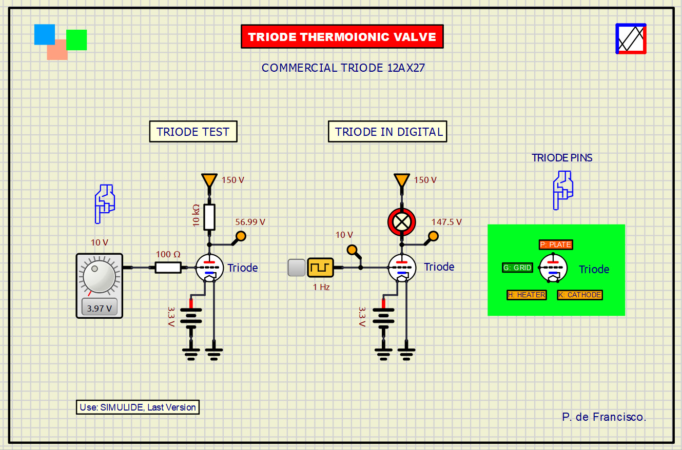
The schematic contains two examples: an analog test and the transmission of a digital signal.
You can perform further exercises with the triode in this same directory simply by copying its body to another schematic within that directory. If you wish to use this component as a Simulide subcircuit, you must adhere to the simulator's established conventions for doing so.P. deFrancisco.
The thermionic valve is the predecessor to the transistor; it marked the beginning of the world of electronics. Since its invention by Lee de Forest (1873–1961) in 1906, it has been a highly successful component in audio amplification, long-distance telephony, radio and television transmission and reception, industrial applications, and even the early stages of computing.
Operating within an absolute vacuum inside the valve, it functions based on the emission of electrons from an incandescent filament; these electrons are attracted to the plate, which must always maintain a positive bias. The filament is enclosed by a metal cylinder known as the cathode, which—being connected to the filament—regulates the flow of electrons. Situated between the cathode and the plate is the grid, a perforated cylinder that controls the electron flow toward the plate, thereby generating signal gain at the plate.
The subcircuit proposed here was created by first writing a script and subsequently adapting it to add a graphical layer. Below, we present the commented text of the "as" script (AngelScript).
// TRIODE THERMOIONIC VALVE. DEFRAN26

IoPin@ H=component.getPin("H");  // Filamento +3.3 V
IoPin@ K=component.getPin("K");  // Catodo + extremo filamento
IoPin@ G=component.getPin("G");  // Rejilla
IoPin@ P=component.getPin("P");  // Placa
double ganancia = 20.0;
double kTriodo=0.00020;  // Constante de corriente del triodo.
double R_OFF = 1000000000.0;  // Limites...
double R_MIN = 100.0;
double I_MAX = 0.050;
bool actualizando = false;

void setup()
{
  print("Triodo inicializado");
}

void reset()
{
  H.setPinMode(1);
  K.setPinMode(1);
  G.setPinMode(1);
  P.setPinMode(3);  // La placa, Salida con impedancia variable hacia el catodo
  H.changeCallBack(element, true);
  K.changeCallBack(element, true);
  G.changeCallBack(element, true);
  P.changeCallBack(element, true);
  actualizarTriodo();
}

void voltChanged()
{
  actualizarTriodo();
}

void setGanancia(double val)  // PROPIEDAD GANANCIA
{
  if (val < 2.0)  val = 2.0;
  if (val > 200.0) val = 200.0;
  ganancia = val;
  actualizarTriodo();
}

double getGanancia()
{
  return ganancia;
}

void actualizarTriodo()  // MODELO DEL TRIODO
{
  if (actualizando) return;
  actualizando = true;
  double vh  = H.getVoltage();
  double vk  = K.getVoltage();
  double vg  = G.getVoltage();
  double vp  = P.getVoltage();
  double vf = vh - vk;   // TENSION DEL FILAMENTO
  if (vf < 0.0) vf = -vf;
  double calor = 0.0;  // FACTOR DE CALENTAMIENTO
  if (vf <= 2.0) {calor = 0.0;}
  else if (vf >= 3.3) {calor = 1.0;}
  else {calor = (vf - 2.0) / 1.3;}
  double vgk = vg - vk;  // TENSIONES REFERIDAS AL CATODO
  double vpk = vp - vk;
  if ((calor <= 0.0) || (vpk <= 0.0))  // VALVULA APAGADA
  {
     P.setVoltage(vk);
     P.setImpedance(R_OFF);
     actualizando = false;
     return;
  }
  // ECUACION SIMPLIFICADA DEL TRIODO: Vef Vgk+Vpk/mu, mu=ganancia
  double vef = vgk + vpk / ganancia;
  if (vef <= 0.0)  // CORTE
  {
    P.setVoltage(vk);
    P.setImpedance(R_OFF);
    actualizando = false;
    return;
  }
  // CORRIENTE DE PLACA. Aproximacion cuadratica: Ia = K * Vef^2
  double ia = kTriodo * vef * vef;
  ia = ia * calor;
  if (ia > I_MAX) {ia = I_MAX;}  // LIMITAR CORRIENTE MAXIMA
  // CONVERTIR Ia EN RESISTENCIA DINAMICA: R = Vpk / Ia
  double rp;
  if (ia < 0.000001) {rp = R_OFF;}
  else {rp = vpk / ia;}
  if (rp < R_MIN) {rp = R_MIN;}
  if (rp > R_OFF) {rp = R_OFF;}
  P.setVoltage(vk);  // La placa conduce hacia el catodo
  P.setImpedance(rp);
  actualizando = false;
}
All necessary files are packaged in a ZIP archive; this must be extracted into Simulide's "test" directory, where the simulation can be launched simply by running the "Triode_Test.sim1" file.
The schematic contains two examples: an analog test and the transmission of a digital signal.
You can perform further exercises with the triode in this same directory simply by copying its body to another schematic within that directory. If you wish to use this component as a Simulide subcircuit, you must adhere to the simulator's established conventions for doing so.
P. deFrancisco.
Uploaded files: