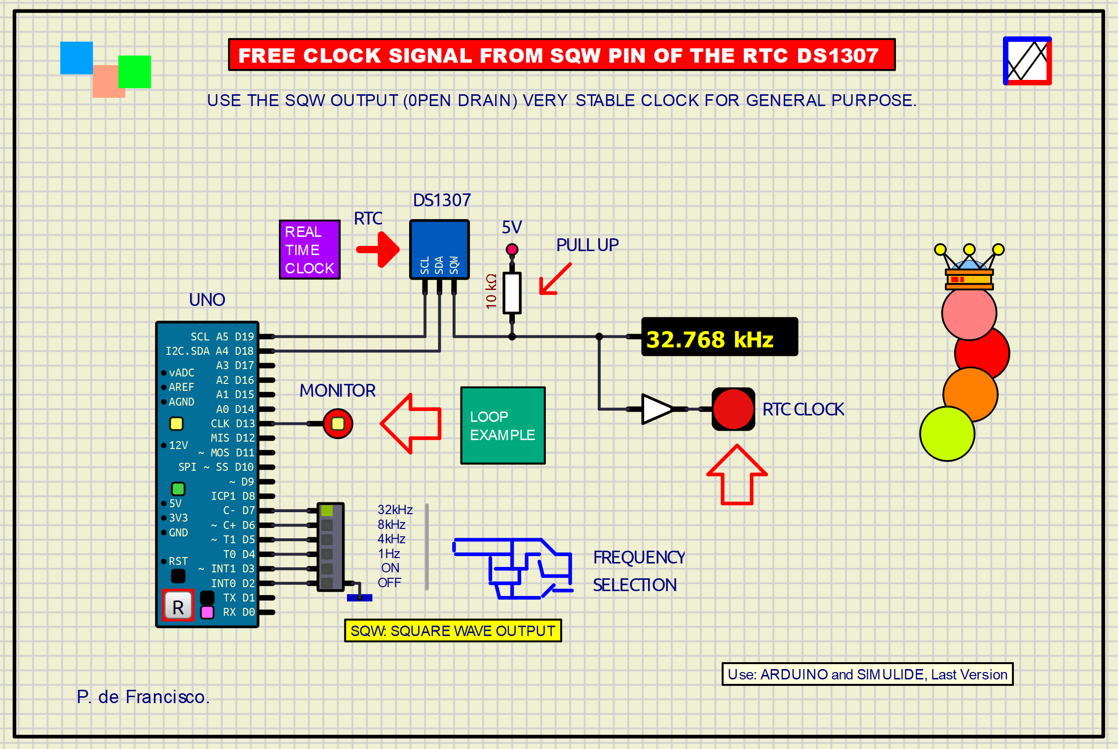
366_RTC SQW OUTPUT STABLE CLOCK
Quote from Defran on October 30, 2024, 11:10 am
366_RTC SQW OUTPUT STABLE CLOCK. (Simulide 1.1.1973 or Higher).
The RTC (Real Time Clock) DS1307 and the RTC DS3231 (a much improved RTC that includes ambient temperature data) are two devices capable of delivering clock and calendar data via I2C so that they can be collected by the controller and used for various purposes (Clocks, timers, etc.). These RTCs have an output called SQW (Square Wave Output) that provides clock signals with the stability provided by the internal quartz crystal. These frequencies are 32768 kHz, 8192 kHz, 4096 kHz and 1 Hz. These signals can be used as general purpose within the schematic design.
A 6-position switch is used to select the output frequency marked plus the ON and OFF positions to enable or disable the signal output. An LED connected to the SQW output has also been added to display the signal, which will only flash for 1Hz, for the other frequencies it will simply light up when there is a signal present. A second LED flashes continuously at 1 HZ as a functioning monitor.
Technical information of these two RTCs:
https://www.alldatasheet.com/datasheet-pdf/download/58481/DALLAS/DS1307.html
https://www.alldatasheet.com/datasheet-pdf/download/112132/DALLAS/DS3231.htmlSCHEME:
The schematic is based on the Arduino UNO. In this example we use the RTC DS1307 connected by I2C. It is a very simple schematic for this purpose where you can see the connection of the devices discussed. The SQW output only delivers a signal if it has been configured in the software
PROGRAMA:
The external library used is: RTClib.h
// RTC DS307. STABLE CLOCK SIGNAL FROM SQW PIN. DEFRAN 24. #include <RTClib.h> #define RTC_ADDR 0x68 // RTC ADDRESS int Fset; Ds1307SqwPinMode Freq[]={DS1307_OFF, DS1307_ON, DS1307_SquareWave1HZ, DS1307_SquareWave4kHz, DS1307_SquareWave8kHz, DS1307_SquareWave32kHz}; RTC_DS1307 RTC; void setup() { pinMode(13, OUTPUT); // Monitor RTC.begin(); int pines[]={2,3,4,5,6,7}; for(int i=0; i<6; i++) {pinMode(pines[i], INPUT_PULLUP);} } void loop() { if(digitalRead(2)==LOW) Fset=0; // OFF if(digitalRead(3)==LOW) Fset=1; // ON if(digitalRead(4)==LOW) Fset=2; // 1K if(digitalRead(5)==LOW) Fset=3; // 4K if(digitalRead(6)==LOW) Fset=4; // 8K if(digitalRead(7)==LOW) Fset=5; // 32K RTC.writeSqwPinMode(Freq[Fset]); digitalWrite(13,1); delay(1200); digitalWrite(13,0); // Monitor delay(800); }SUBCIRCUITS:This example integrates several subcircuits located in the "data" folder into the ZIP attached. This folder must always be next to the "sim1" scheme so that it can be executed. A subcircuit is a “custom” circuit that accumulates a set of Simulide base components (primitive function) to obtain a new or an adapted function. These subcircuits are treated by Simulide as another component of its own structure. User can create his own subcircuits or use the ones published here in your own designs once the procedure is known, explained in detail in the Simulide tutorials: https://simulide.com/p/subcircuits/More examples for Simulide are here: https://simulide.forumotion.com/f12-projects-made-in-simulide* Communication with the author: Simulide/User/Messages/DefranP. de Francisco.

366_RTC SQW OUTPUT STABLE CLOCK. (Simulide 1.1.1973 or Higher).
The RTC (Real Time Clock) DS1307 and the RTC DS3231 (a much improved RTC that includes ambient temperature data) are two devices capable of delivering clock and calendar data via I2C so that they can be collected by the controller and used for various purposes (Clocks, timers, etc.). These RTCs have an output called SQW (Square Wave Output) that provides clock signals with the stability provided by the internal quartz crystal. These frequencies are 32768 kHz, 8192 kHz, 4096 kHz and 1 Hz. These signals can be used as general purpose within the schematic design.
A 6-position switch is used to select the output frequency marked plus the ON and OFF positions to enable or disable the signal output. An LED connected to the SQW output has also been added to display the signal, which will only flash for 1Hz, for the other frequencies it will simply light up when there is a signal present. A second LED flashes continuously at 1 HZ as a functioning monitor.
Technical information of these two RTCs:
https://www.alldatasheet.com/datasheet-pdf/download/58481/DALLAS/DS1307.html
https://www.alldatasheet.com/datasheet-pdf/download/112132/DALLAS/DS3231.html
SCHEME:
PROGRAMA:
The external library used is: RTClib.h
// RTC DS307. STABLE CLOCK SIGNAL FROM SQW PIN. DEFRAN 24.

#include <RTClib.h>
#define RTC_ADDR 0x68  // RTC ADDRESS
int Fset;
Ds1307SqwPinMode Freq[]={DS1307_OFF, DS1307_ON, DS1307_SquareWave1HZ, DS1307_SquareWave4kHz, DS1307_SquareWave8kHz, DS1307_SquareWave32kHz};
RTC_DS1307 RTC;

void setup()
{
  pinMode(13, OUTPUT);  // Monitor
  RTC.begin();
  int pines[]={2,3,4,5,6,7};
  for(int i=0; i<6; i++) {pinMode(pines[i], INPUT_PULLUP);}
}

void loop()
{
  if(digitalRead(2)==LOW) Fset=0;   // OFF
  if(digitalRead(3)==LOW) Fset=1;   // ON
  if(digitalRead(4)==LOW) Fset=2;   // 1K
  if(digitalRead(5)==LOW) Fset=3;   // 4K
  if(digitalRead(6)==LOW) Fset=4;   // 8K
  if(digitalRead(7)==LOW) Fset=5;   // 32K
  RTC.writeSqwPinMode(Freq[Fset]);
  digitalWrite(13,1);
  delay(1200);
  digitalWrite(13,0);  // Monitor
  delay(800);
}