
362__COUNTDOWN BY KEYBOARD
Quote from Defran on March 22, 2024, 12:41 am
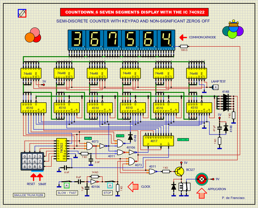
362__COUNTDOWN BY KEYBOARD. (simulide R2259 or higher).
This is a Countdown of six digits designed with semi-discrete components, that is, with standard integrated circuits. Doing this now when there are more evolved devices such as controllers does not make sense if it is not for some type of challenge or for the purpose of practice (as is our case). The count is presented on a 6-digit seven-segment LED display whose number is entered by a matrix keyboard served by the specific integrated circuit 74C922. The number entered moves to the left, leaving the digits on the left that are zero always turned off. With the [S] START key the counting starts and with the [R] RESET key the counter is cleared and stopped. At the output of the counter, a relay activates the circuit applied to its contacts when the counter starts and is deactivated when the count reaches zero or [RESET] is pressed. The clock signal is an oscillator that provides two different selectable frequencies that we have called FAST and SLOW (seconds) and a second [STOP] switch to temporarily stop the count.
SCHEME:
The 6-digit independent display with 7 segments-LEDs (common cathode) is served by 7-segment BCD decoders (74x48) inside which the LED resistors are already included. This decoder has the LT (Lamp Test) input to turn on all the segments of all the digits as a test. The RI, BI/RO inputs make up a structure that turns off the digits on the left that are at zero. All the BCD outputs of the previous counter (4510) go to the preset inputs of the subsequent counter to obtain the effect of shifting the numbers. The CO outputs are connected to a 6-bit OR gate (made with diodes) to detect when all the counters are at zero. Circuit 4017 performs the left shift process by controlling the PE inputs of the counters. The 74C922 integrated circuit serves the matrix keyboard. The clock signal generated by this is also used for the 4017. The outputs of the 74C922 are applied to the first preset inputs of the first counter IC and also to two three-input AND gates (4073) that "decode" the state of the keys. [R] and [S] on the keyboard to clear or start the counter respectively. The oscillator is a Schmitt inverter (40106) that produces two frequencies: FAST as a base and SLOW (Seconds), the latter when the SLOW/FAST switch is closed. The STOP switch causes the counting to stop simply by interrupting the clock signal.
To Know more about the 74C922: https://www.datasheet4u.com/mobile/243040/74C922.html
SUBCIRCUITS:This example integrates several subcircuits located in the "data" folder into the ZIP attached. This folder must always be next to the "sim1" scheme so that it can be executed. A subcircuit is a “custom” circuit that accumulates a set of Simulide base components (primitive function) to obtain a new or an adapted function. These subcircuits are treated by Simulide as another component of its own structure. User can create his own subcircuits or use the ones published here in your own designs once the procedure is known, explained in detail in the Simulide tutorials: https://simulide.com/p/subcircuits/* Communication with the author: Simulide/User/Messages/DefranP. de Francisco.
362__COUNTDOWN BY KEYBOARD. (simulide R2259 or higher).
This is a Countdown of six digits designed with semi-discrete components, that is, with standard integrated circuits. Doing this now when there are more evolved devices such as controllers does not make sense if it is not for some type of challenge or for the purpose of practice (as is our case). The count is presented on a 6-digit seven-segment LED display whose number is entered by a matrix keyboard served by the specific integrated circuit 74C922. The number entered moves to the left, leaving the digits on the left that are zero always turned off. With the [S] START key the counting starts and with the [R] RESET key the counter is cleared and stopped. At the output of the counter, a relay activates the circuit applied to its contacts when the counter starts and is deactivated when the count reaches zero or [RESET] is pressed. The clock signal is an oscillator that provides two different selectable frequencies that we have called FAST and SLOW (seconds) and a second [STOP] switch to temporarily stop the count.
SCHEME:
The 6-digit independent display with 7 segments-LEDs (common cathode) is served by 7-segment BCD decoders (74x48) inside which the LED resistors are already included. This decoder has the LT (Lamp Test) input to turn on all the segments of all the digits as a test. The RI, BI/RO inputs make up a structure that turns off the digits on the left that are at zero. All the BCD outputs of the previous counter (4510) go to the preset inputs of the subsequent counter to obtain the effect of shifting the numbers. The CO outputs are connected to a 6-bit OR gate (made with diodes) to detect when all the counters are at zero. Circuit 4017 performs the left shift process by controlling the PE inputs of the counters. The 74C922 integrated circuit serves the matrix keyboard. The clock signal generated by this is also used for the 4017. The outputs of the 74C922 are applied to the first preset inputs of the first counter IC and also to two three-input AND gates (4073) that "decode" the state of the keys. [R] and [S] on the keyboard to clear or start the counter respectively. The oscillator is a Schmitt inverter (40106) that produces two frequencies: FAST as a base and SLOW (Seconds), the latter when the SLOW/FAST switch is closed. The STOP switch causes the counting to stop simply by interrupting the clock signal.
To Know more about the 74C922: https://www.datasheet4u.com/mobile/243040/74C922.html