
361__DIGITAL POTENTIOMETER_PRACTICE
Quote from Defran on March 17, 2024, 8:46 pm
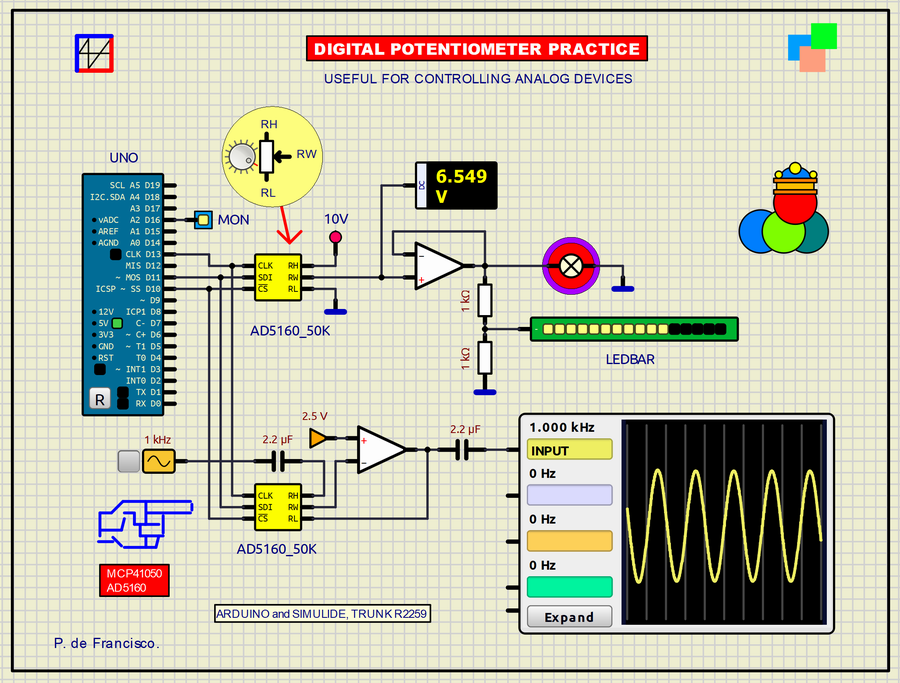
361_DIGITAL POTENTIOMETER_PRACTICE. (Simulide R2259 or Higher).
The component we use here is a potentiometer that is controlled digitally, in this case by SPI. The potentiometer itself behaves like a normal potentiometer with its three free terminals (RH, RL and RW) so that the user can connect them freely in the analog circuit to be controlled. Here we use two MCP41050 or AD5160 connected in parallel to the SPI terminals of the controller (CLK pin D13, MOSI pin D11 and SS pin 10). In the first, the amplified output goes to a lamp, a voltmeter and a LED bar to see the incremental signal delivered by the controller. The second is used in the feedback loop of an Opamp. The dynamic signal is seen on the oscilloscope cyclically.
SCHEME:
The scheme is very simple and self-explanatory. The upper digital potentiometer is amplified in current and applied to the three devices mentioned. The regulation voltage is 10V so at the input of the LED bar you have to put a /2 divider because it only accepts 5V signals. In the lower digital potentiometer, a 1V sinusoid is used that is applied to the opamp through the digital potentiometer in a circuit doubly decoupled in DC by two capacitors. The MON LED monitors the signal when it is in the input phase and the middle of the output sequence.
PROGRAM:
The program (in Arduino C) uses the internal SPI library in its IDE. Here the library commands are used in the two functional phases: The first in a single execution setup showing the signal at five fixed points. The second in the program loop, sampling is done throughout the entire signal path forward and backward continuously.
// DIGITAL POTENTIOMETER PRACTICE . DEFRAN24 #include <SPI.h> // SPI PINS: CLK-13, SDI-11, SS-10 const int CS=10; // SS of SPI int MON=16; void setup() { pinMode (MON, OUTPUT); pinMode (CS, OUTPUT); SPI.begin(); digitalWrite(MON, HIGH); PotWrite(0); delay(400); PotWrite(63); delay(400); PotWrite(127); delay(400); PotWrite(192); delay(400); PotWrite(255); delay(400); digitalWrite(MON, LOW); } void loop() { for (int i=0; i<=255; i++) { PotWrite(i); delay(10); } delay(500); digitalWrite(MON, HIGH); for (int i=255; i>=0; i--) { PotWrite(i); delay(10); } digitalWrite(MON, LOW); delay(500); digitalWrite(MON, LOW); } int PotWrite(int value) { // COMMAND BYTE: xxDCxxBA: A-POT1, B-PO2, C-POT VALUE, D-SHUTDOWN digitalWrite(CS, LOW); // SS of SPI) SPI.transfer(0b00010001); //command SPI.transfer(value); //value digitalWrite(CS, HIGH); // SS OF SPI) }SUBCIRCUITS:This example integrates several subcircuits located in the "data" folder into the ZIP attached. This folder must always be next to the "sim1" scheme so that it can be executed. A subcircuit is a “custom” circuit that accumulates a set of Simulide base components (primitive function) to obtain a new or an adapted function. These subcircuits are treated by Simulide as another component of its own structure. User can create his own subcircuits or use the ones published here in your own designs once the procedure is known, explained in detail in the Simulide tutorials: https://simulide.com/p/subcircuits/* Communication with the author: Simulide/User/Messages/DefranP. de Francisco.
361_DIGITAL POTENTIOMETER_PRACTICE. (Simulide R2259 or Higher).
The component we use here is a potentiometer that is controlled digitally, in this case by SPI. The potentiometer itself behaves like a normal potentiometer with its three free terminals (RH, RL and RW) so that the user can connect them freely in the analog circuit to be controlled. Here we use two MCP41050 or AD5160 connected in parallel to the SPI terminals of the controller (CLK pin D13, MOSI pin D11 and SS pin 10). In the first, the amplified output goes to a lamp, a voltmeter and a LED bar to see the incremental signal delivered by the controller. The second is used in the feedback loop of an Opamp. The dynamic signal is seen on the oscilloscope cyclically.
SCHEME:
The scheme is very simple and self-explanatory. The upper digital potentiometer is amplified in current and applied to the three devices mentioned. The regulation voltage is 10V so at the input of the LED bar you have to put a /2 divider because it only accepts 5V signals. In the lower digital potentiometer, a 1V sinusoid is used that is applied to the opamp through the digital potentiometer in a circuit doubly decoupled in DC by two capacitors. The MON LED monitors the signal when it is in the input phase and the middle of the output sequence.
PROGRAM:
The program (in Arduino C) uses the internal SPI library in its IDE. Here the library commands are used in the two functional phases: The first in a single execution setup showing the signal at five fixed points. The second in the program loop, sampling is done throughout the entire signal path forward and backward continuously.
// DIGITAL POTENTIOMETER PRACTICE . DEFRAN24

#include <SPI.h>  // SPI PINS: CLK-13, SDI-11, SS-10
const int CS=10;  // SS of SPI
int MON=16;

void setup()
{
  pinMode (MON, OUTPUT);
  pinMode (CS, OUTPUT);
  SPI.begin();
  digitalWrite(MON, HIGH);
  PotWrite(0);   delay(400);
  PotWrite(63);  delay(400);
  PotWrite(127); delay(400);
  PotWrite(192); delay(400);
  PotWrite(255); delay(400);
  digitalWrite(MON, LOW);
}

void loop()
{
  for (int i=0; i<=255; i++)
  {
    PotWrite(i);
    delay(10);
  }
  delay(500);
  digitalWrite(MON, HIGH);
  for (int i=255; i>=0; i--)
  {
    PotWrite(i);
    delay(10);
  }
  digitalWrite(MON, LOW);
  delay(500);
  digitalWrite(MON, LOW);
}

int PotWrite(int value)
{
  // COMMAND BYTE: xxDCxxBA: A-POT1, B-PO2, C-POT VALUE, D-SHUTDOWN
  digitalWrite(CS, LOW);    // SS of SPI)
  SPI.transfer(0b00010001); //command
  SPI.transfer(value);      //value
  digitalWrite(CS, HIGH);   // SS OF SPI)
}