
360__POSITIVE PULSE WIDTH CONTROL IN A SQUARE WAVE
Quote from Defran on March 12, 2024, 7:16 pm
360_POSITIVE PULSE WIDTH CONTROL IN A SQUARE WAVE. (simulide R2220 or Higher).
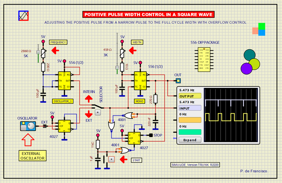
We present here a circuit to control the total width of the positive pulse of a square wave at a fixed frequency (from a very narrow positive pulse to practically the entire period). The frequency is adjusted with the oscillator potentiometer marked FREQUENCY and the pulse width is adjusted with the WIDTH potentiometer. A switch has also been included to select a possible external oscillator. If the width value is set longer than the period of the selected frequency, an overflow effect occurs, which is controlled here by blocking the output by going to LOW state. To exit this state you must set the WIDTH potentiometer to minimum and press the [START] button.
SCHEME:The electrical diagram is based on the 556 integrated circuit that integrates two 555s. The first "555 block" forms a user-controllable oscillator whose output always gives a very narrow pulse at any frequency, that is so as not to affect the timing control of the second part composed of another "block 555" that forms a monostable adjustable by the user. At the output you can see both waves on the oscilloscope and on the LED as an output monitor. The SELECTOR switch can switch between the internal 556 oscillator and an external square wave oscillator, whose positive pulse is narrowed by a JK type flip-flop (4027). This action is achieved by joining the NOT Q output with the preset. Its output is applied to monstable (another 555 of the 556) to control the output from a narrow pulse to almost the period of the selected frequency.The circuit that controls the overflow is based on NOR gates to detect the moment when the oscillator pulse is LOW and the monostable pulse remains HIGH, then this signal is applied to the CK input of another Flip flop (4027) whose output resets the MONO 556, so the output goes to a constant LOW level. Pressing the [START] button resets the Flip flop and the cycle continues as long as the WIDTH potentiometer is at a non-overflow value.To know more about The 556: https://www.ti.com/lit/ds/symlink/ne556.pdf?ts=1710339448429&ref_url=https%253A%252F%252Fwww.google.com%252FSUBCIRCUITS:This example integrates several subcircuits located in the "data" folder into the ZIP attached. This folder must always be next to the "sim1" scheme so that it can be executed. A subcircuit is a “custom” circuit that accumulates a set of Simulide base components (primitive function) to obtain a new or an adapted function. These subcircuits are treated by Simulide as another component of its own structure. User can create his own subcircuits or use the ones published here in your own designs once the procedure is known, explained in detail in the Simulide tutorials: https://simulide.com/p/subcircuits/* Communication with the author: Simulide/User/Messages/DefranP. de Francisco.

360_POSITIVE PULSE WIDTH CONTROL IN A SQUARE WAVE. (simulide R2220 or Higher).
We present here a circuit to control the total width of the positive pulse of a square wave at a fixed frequency (from a very narrow positive pulse to practically the entire period). The frequency is adjusted with the oscillator potentiometer marked FREQUENCY and the pulse width is adjusted with the WIDTH potentiometer. A switch has also been included to select a possible external oscillator. If the width value is set longer than the period of the selected frequency, an overflow effect occurs, which is controlled here by blocking the output by going to LOW state. To exit this state you must set the WIDTH potentiometer to minimum and press the [START] button.