356__INTERNAL FUNCTIONAL SCHEME OF THE 555
Quote from Defran on March 3, 2024, 1:15 pm
356_INTERNAL FUNCTIONAL SCHEME OF THE 555 (Simulide R2220 or Higher).
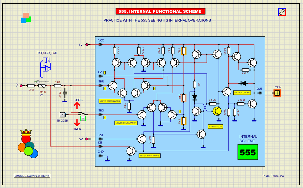
The successful 555 integrated circuit was created in the early seventies as an oscillator and timer, then based on its structure tens of different circuitry applications have been found. We in this example with its visible structure configure it as an oscillator and as a timer and to do this it is enough to position the switch in the position of the desired function. A sliding potentiometer has been added to vary the frequency in the case of an oscillator or as a time adjustment in the case of a monostable or timer. At the output, an LED shows the status of its output, shining when the level is HIGH.
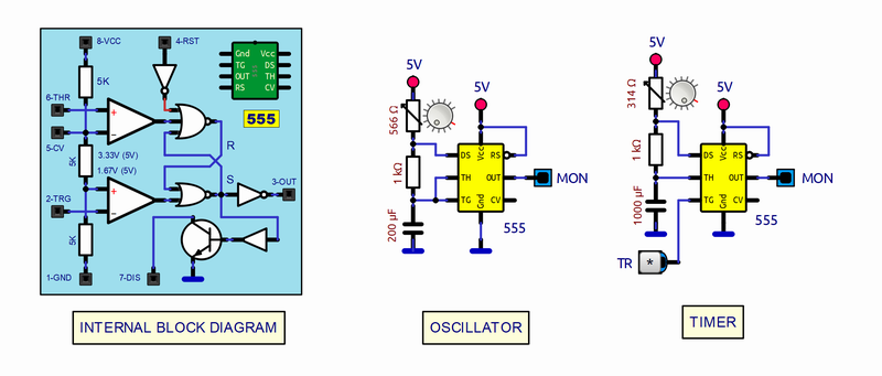
SCHEME:Our diagram shows the internal structure of the 555 composed of standard PNP and NPN bipolar transistors that basically configure five functional areas:1) Upper Comparator with THR (Thereshold) and CV (Control Voltage) inputs2) Lower Comparator with TRG (Trigger) input3) Flip-Flip type RS.4) Output Driver5) RST (Reset) and DIS (External Capacitor Discharge) circuit.Discussing operation in detail is not the purpose of this article, but it is easy to recognize the structures and follow their signals and voltages when starting it up. For its operation, there is a voltage divider with three 5k resistors (Marked with an orange background), which make up the reference voltages for the comparators, 1/3 of the supply voltage, which for 5V would be: 3.33V for the HIGH level and 1.67V for the LOW level. As can be seen, all the control signals converge in the Flip-flop, which is the agent of the operation, at whose output are: The output driver and the transistor for the discharge of the external capacitor (As a feedback element) when the output goes to a LOW level.We also add in the previous figure the equivalent circuit of the 555 (With standard graphic components) and the two typical application examples mentioned here: Oscillator and timer with the 555 encapsulated in 8-pin DIP, the most used for this integrated circuit.To learn more about the 555: https://www.ti.com/lit/ds/symlink/lm555.pdf?ts=1709509654485&ref_url=https%253A%252F%252Fwww.google.com%252FSUBCIRCUITS:This example integrates several subcircuits located in the "data" folder into the ZIP attached. This folder must always be next to the "sim1" scheme so that it can be executed. A subcircuit is a “custom” circuit that accumulates a set of Simulide base components (primitive function) to obtain a new or an adapted function. These subcircuits are treated by Simulide as another component of its own structure. User can create his own subcircuits or use the ones published here in your own designs once the procedure is known, explained in detail in the Simulide tutorials: https://simulide.com/p/subcircuits/* Communication with the author: Simulide/User/Messages/DefranP. de Francisco.
356_INTERNAL FUNCTIONAL SCHEME OF THE 555 (Simulide R2220 or Higher).
The successful 555 integrated circuit was created in the early seventies as an oscillator and timer, then based on its structure tens of different circuitry applications have been found. We in this example with its visible structure configure it as an oscillator and as a timer and to do this it is enough to position the switch in the position of the desired function. A sliding potentiometer has been added to vary the frequency in the case of an oscillator or as a time adjustment in the case of a monostable or timer. At the output, an LED shows the status of its output, shining when the level is HIGH.