
355__CURRENT MEASUREMENT AND LIMIT WITH I2C_LCD
Quote from Defran on February 26, 2024, 1:54 pm
355__CURRENT MEASUREMENT AND LIMIT WITH I2C_LCD. (Simulide_R2194 or Higher)
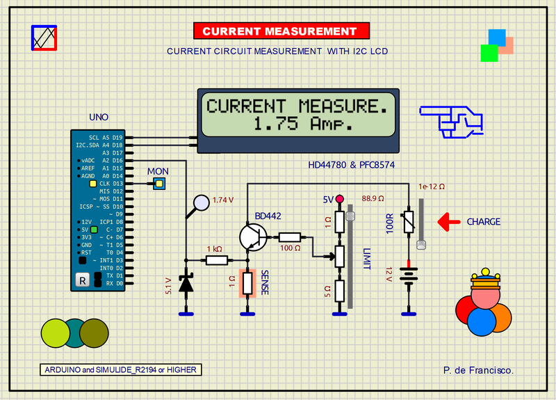
This example is a simple DC courrent meter. The powe supply is a 12V battery in whose circuit are found in series: a variable CHARGE resistor, a transistor for current limitation and a 1 ohm resistor as a sensor element to take the sample that enters the controller through the terminal analog A2. With the SETTING LIMIT potentiometer you can adjust the current limit and with the CHARGE potentiometer you can change the current. The current value is shown on the LCD display in amperes (16x2 lines). The MON LED lights up when the current exceeds one ampere.
SCHEME:
The scheme is composed of a circuit through which the application current passes from a 12V battery. In the circuit are the charge resistor, the limitation circuit and the current measurement resistor. The display is an LCD composed of two parts: The HDD44780 display with 16x2 lines with individualized inputs and the I2C to 8-bit parallel converter PFC8574, these two modules usually come mounted on top of each other in an I2C communication solution with the controller Arduino UNO. The 5.1V zener is a voltage protection for the A2 INPUT.
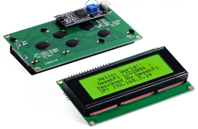
The following figure shows a commercial example of I2C LCD with this solution:
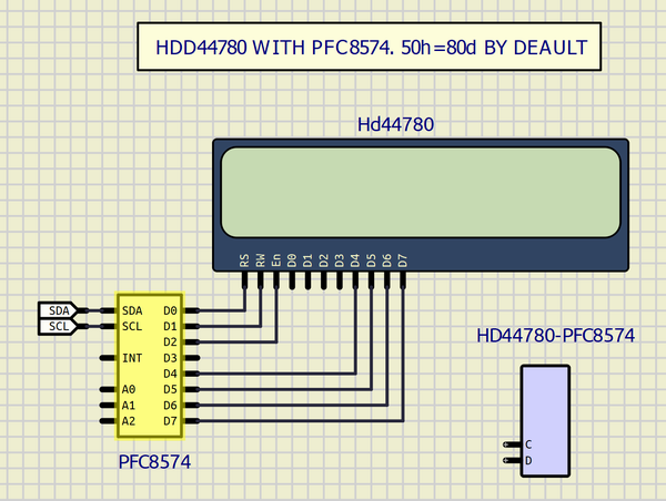
These two components of the LCD have been included in the subcircuit HDD4480-PFC8574 used here and shown below:
PROGRAM:
This program is in C of Arduino. The libraries
LiquidCrystal_I2C.handWire.hare internal in Arduino IDE.// MEASUREMENT AND LIMIT OF A DC CURRENT CIRCUIT. DEFRAN24. #include <Wire.h> #include <LiquidCrystal_I2C.h> #define I2C_ADDR 0x50 int BACKLIGHT=3; LiquidCrystal_I2C lcd(I2C_ADDR,2,1,0,4,5,6,7); // Address and PFC8574 pins unsigned long time, differ; float ampe=0; int MON=13; int sense=A2; // Sense INPUT void setup() { pinMode(MON, OUTPUT); lcd.begin(16,2); lcd.setBacklightPin(BACKLIGHT,POSITIVE); lcd.setBacklight(HIGH); lcd.home(); lcd.print("CURRENT MEASURE."); } void loop() { differ=millis()-time; if (differ >= 200) { ampe=(map(analogRead(sense), 0,1024, 0,507))/100.0f; // MAP, CALIB AND DECIMALS. if( ampe > 1) digitalWrite(MON,HIGH); else digitalWrite(MON,LOW); lcd.setCursor(4,1); lcd.print(ampe); lcd.print(" Amp. "); time = millis(); } }SUBCIRCUITS:This example integrates several subcircuits located in the "data" folder into the ZIP attached. This folder must always be next to the "sim1" scheme so that it can be executed. A subcircuit is a “custom” circuit that accumulates a set of Simulide base components (primitive function) to obtain a new or an adapted function. These subcircuits are treated by Simulide as another component of its own structure. User can create his own subcircuits or use the ones published here in your own designs once the procedure is known, explained in detail in the Simulide tutorials: https://simulide.com/p/subcircuits/* Communication with the author: Simulide/User/Messages/DefranP. de Francisco.
355__CURRENT MEASUREMENT AND LIMIT WITH I2C_LCD. (Simulide_R2194 or Higher)
This example is a simple DC courrent meter. The powe supply is a 12V battery in whose circuit are found in series: a variable CHARGE resistor, a transistor for current limitation and a 1 ohm resistor as a sensor element to take the sample that enters the controller through the terminal analog A2. With the SETTING LIMIT potentiometer you can adjust the current limit and with the CHARGE potentiometer you can change the current. The current value is shown on the LCD display in amperes (16x2 lines). The MON LED lights up when the current exceeds one ampere.
SCHEME:
The scheme is composed of a circuit through which the application current passes from a 12V battery. In the circuit are the charge resistor, the limitation circuit and the current measurement resistor. The display is an LCD composed of two parts: The HDD44780 display with 16x2 lines with individualized inputs and the I2C to 8-bit parallel converter PFC8574, these two modules usually come mounted on top of each other in an I2C communication solution with the controller Arduino UNO. The 5.1V zener is a voltage protection for the A2 INPUT.
The following figure shows a commercial example of I2C LCD with this solution:
These two components of the LCD have been included in the subcircuit HDD4480-PFC8574 used here and shown below:
PROGRAM:
This program is in C of Arduino. The libraries LiquidCrystal_I2C.h and Wire.h are internal in Arduino IDE.
// MEASUREMENT AND LIMIT OF A DC CURRENT CIRCUIT. DEFRAN24.

#include <Wire.h>
#include <LiquidCrystal_I2C.h>
#define I2C_ADDR 0x50
int BACKLIGHT=3;
LiquidCrystal_I2C lcd(I2C_ADDR,2,1,0,4,5,6,7); // Address and PFC8574 pins
unsigned long time, differ;
float ampe=0;
int MON=13;
int sense=A2;   // Sense INPUT

void setup()
{
  pinMode(MON, OUTPUT);
  lcd.begin(16,2);
  lcd.setBacklightPin(BACKLIGHT,POSITIVE);
  lcd.setBacklight(HIGH);
  lcd.home();
  lcd.print("CURRENT MEASURE.");
}

void loop()
{
  differ=millis()-time;
  if (differ >= 200)
  {
    ampe=(map(analogRead(sense), 0,1024, 0,507))/100.0f;  // MAP, CALIB AND DECIMALS.
    if( ampe > 1) digitalWrite(MON,HIGH);
    else digitalWrite(MON,LOW);
    lcd.setCursor(4,1);
    lcd.print(ampe);
    lcd.print(" Amp.   ");
    time = millis();
  }
}