
353__ TIMER WITH AUTODISCONNECTION WITH TINY85 AND "timer0"
Quote from Defran on February 18, 2024, 3:50 pm
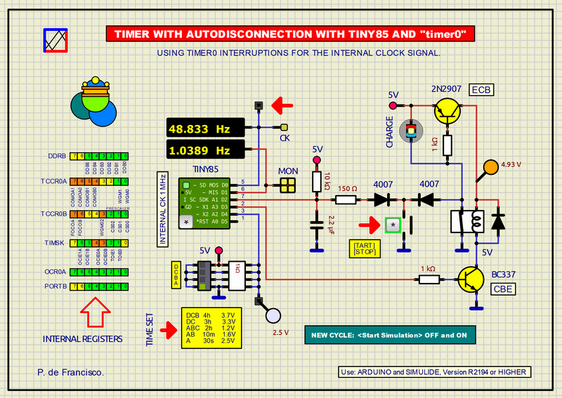
353_ TIMER WITH AUTODISCONNECTION WITH TINY85 AND "timer0". Simulide R2194 or higher.
This example is a timer with total power disconnection when reaching the end of the preset time. It is designed for smartphone chargers, electric broom chargers and so on. It is based on example 196, https://simulide.forumotion.com/t1296-196__timer-with-disconnection-at-220v, but now using a Tiny85 and the internal timer0 as clock signal. The previous one used the controller from Arduino UNO ATM328 and took the 50Hz clock signal from the electrical network. Using the internal timer gives a little less precision, but for this application it is sufficient and the hardware is more simplified.
USE:
Press the button until the LED starts to light, then release, which begins the timing activating the Relay and the counting sequence on the controller. While the button is pressed the LED will light dimly. To stop manually the timing just press it again, which will deactivate the relay completely disconnecting the timer.
Before starting the timing, the time must be selected according to the table shown in the diagram. During timing the LED will mark each second with a varying relationship between ON and OFF to show the remaining time. At the beginning the LED's on time will be greater than its off time, but this proportion will advance until it approaches the end in which the relationship will be the opposite: The LED's on time will be shorter and the off time will be longer until total extinction. This makes up the working duty cycle.
In the simulator to start a new time cycle you must press the simulator button [STOP SIMULATION] and [START SIMULATION] again. This is to simulate the behavior of the real circuit in which the total power disconnection occurs.
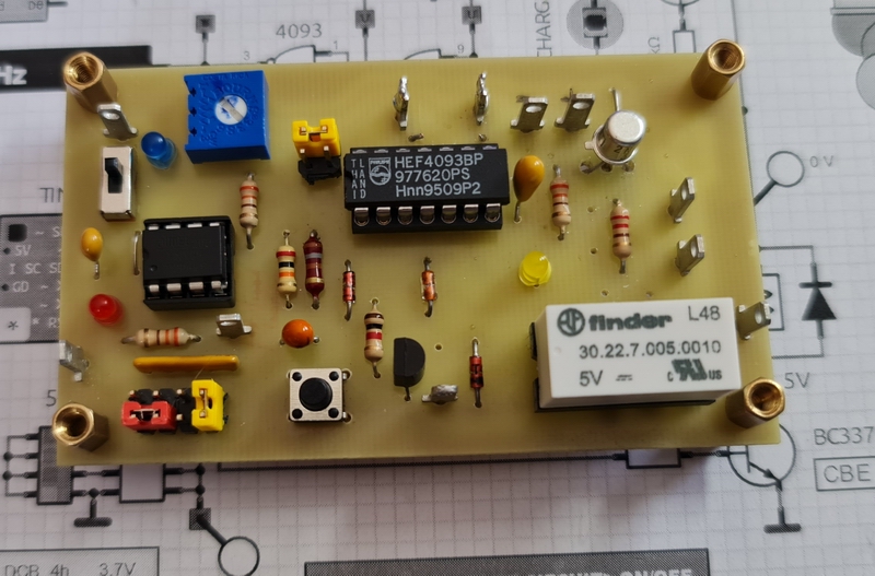
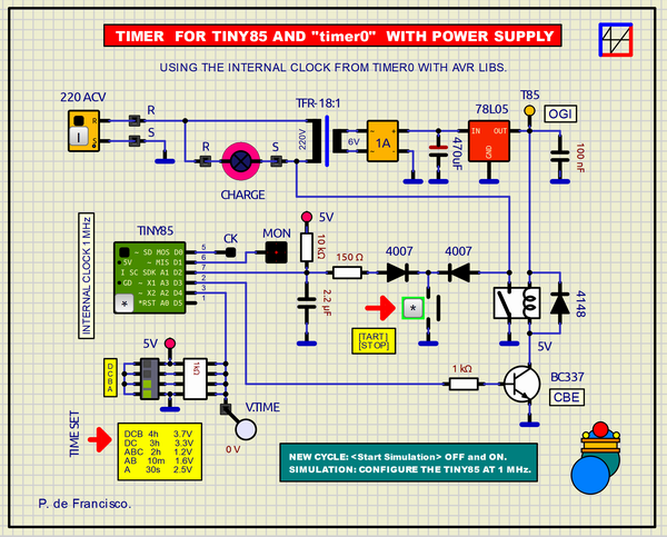
SCHEME:Obviously the heart of the scheme is the Tiny85 controller, which uses three digital outputs for the LEDs and relay and two analogue ones for the button and time selector. The relay is used to connect and disconnect the timer from the power supply. The push button is used to activate the timer, deactivation occurs automatically when the selected time expires and manually at any time during the timing cycle. The button has an analog behavior due to the RC network that intervenes in its microtiming and the elimination of bounces. Pressing the button activates the power supply through the PNP transistor 2N2907, polarizing the base, then the controller program starts by activating the NPN transistor BC337, which introduces a ground level in the relay, thus producing the latching of the relay.Given the functional complexity of the circuit, it has been necessary to test it in reality, in which we have observed with surprise that the commercial tiny85s come pre-programmed with different operating frequencies that can vary from 1 MHz to 16 MHz. Due to this, we must empirically find their frequency "tuning" Simulide and the real circuit. Another operation would be, once the pre-programmed frequency of the Tiny is known, change it to 8MHz (manufacturer's standard frequency) by the procedure of blowing internal fuses, a complex operation that requires certain knowledge and precautions or CHANGE the prescaler values by program, an option adopted in our case. In simulide the internal clock frequency of the Tiny85 can be changed in "properties". In the previous figure we show the hardware developed for these tests.For this example we have proposed a simple scheme in which to see all its operation, but if you want to make a practical scheme and develop it, you would have to use the example of the previous figure and, given that several RLC devices are involved, you have to adjust the reactive value for Simulate about 10 microseconds in its setting. We have tested this circuit also in the reality and it works perfectly. The program would be the same.In the real scheme it is necessary to control the timer hardware at 5V and the power supply at 220 ACV with the same button, so the two 1N4007 diodes are essential, capable of blocking more than 350V in reverse.PROGRAM:This program is in C of Arduino and its details are sufficiently detailed in the line comments. The libraries are from AVR. The diagram shows graphically the structure of the internal registers of the Tiny85 involved in the operation of the timer0 interruption.This program requires to be compiled for Tiny85. It can be compiled using the Arduino IDE or using Simulide by adjusting the Compiler Setting: a) board: custom, b) Custom board: ATTinyCore:avr:attinyx5; but for this the folder "ATTinyCore" must exist in the folder of Arduino like this: Arduino/Hardware/ATTinyCore. A Zip file with AttinyCore is attached along with the project Zip.
The C program is found in source and object in the file attached to this example. And do not forget for R2194 copy the folder "0_ATTiny_84_85_Arduino_Hardware.zip" in Simulide/data/AVR and unzip it there.// TIMER TINY85 WITH INTERNAL CLOCK OF 50Hz FROM "timer0 interrpt". DEFRAN24. // ATTinyCore:avr:attinyx5 Simulide Setting for Tiny85. #include <avr/io.h> #include <avr/interrupt.h> #include <util/delay.h> int MON=1; // LED monitor MON, D1. int RED=0; // LED for 50Hz. int RELE=3; // Relay, D4. int pulsa=A1; // Button A1. Due to the filtering circuit it behaves analogically. int SelTmp=A2; // Resistive network to determine 5 times. int count; // Counter. int conto; // Counter. int ckv=0; // Clock status. int ckpre=0; // Previous data of the button state for the toggle long conta=0; // Time counter satck in ms. int onda=0; // Dutty cycle wave. int SwV=0; // Data from switch and resistive network. int lampv=0; // Lamp variable. long tmax=0; // Max time. int pulsav=0; // Button satus. long pul; // Initial signal. void setup() { pinMode(MON, OUTPUT); // LED MONITOR pinMode(RELE, OUTPUT); // RELAY delay(20); // Delay for the 2.2 uF filter capacitor. START: if(analogRead(pulsa)>500) goto START; // Start by the button. cli(); // Disable global interrupts before initialization DDRB |= (1<<PINB0); // Initialize the PortB Pin0 to output, PINB0 for 50HZ clock TCCR0A = (1<<WGM01); // Initialize the timer0. Put timer0 in CTC mode and clear other bits TCCR0B = (B00000101); // Timer0 prescaling 1024 and clearing other bits TIMSK |= (1<<OCIE0A); // Enable timer1 compare interrupt OCR0A = 10; // Set timer0 count. 255 cycles before to ISR. Higher value higher frequency. PORTB |= (1<<PINB0); // Set PortB Pin1 high to turn on LED sei(); // Initialize global interrupts before beginning loop SwV=analogRead(SelTmp); // Analog reading (0 a 1023). if ((SwV>480)&(SwV<530)) conta=1000; // 20s 511 OFF 2.5V (TEST) if (SwV>750) conta=720000; // 4h 767 DCB 3.7V if ((SwV>650)&(SwV<700)) conta=540000; // 3h 681 DC 3.3V if ((SwV>240)&(SwV<270)) conta=360000; // 2h 255 ABC 1.2V if ((SwV>310)&(SwV<360)) conta=30000; // 10m 341 AB 1.6V tmax=conta; // Maximum time. } void loop() { do { pulsav=analogRead(pulsa); digitalWrite(RELE, HIGH); // RELE ON___ digitalWrite(MON, HIGH); reta(); // LED to HIGH and delay. digitalWrite(MON, LOW); reta(); // LED to LOW and delay. } while (pulsav<300); // Value in LOW do { //___TIMER___ ckv=conto; digitalWrite(RED, ckv); // CLOCK if (ckv!=ckpre){if(ckv==HIGH)conta--; onda++;} // Pulses and wave.. ckpre=ckv; // For Toggle. lampv=(conta*98)/tmax; // Dutty cycle calculation. if (onda<=lampv) digitalWrite(MON, HIGH); // Pulse width to LED MON. else digitalWrite(MON, LOW); if (onda==100) onda=0; // *** (for 50 Hz). SwV=analogRead(SelTmp); do { // ___FORCED STOP OF THE TIMER_____ pulsav=analogRead(pulsa); // Button. if (pulsav<300) // Low level. { digitalWrite(RELE, LOW); // Relay OFF digitalWrite(MON, LOW); // LED OFF STOP: goto STOP; // STOP FOR DISCONNECTION. } } while (pulsav<300); } while (conta!=0); // Output. digitalWrite(MON, LOW); // LED OFF digitalWrite(RELE, LOW); // RELAY OFF. FIN: goto FIN; } ISR(TIM0_COMPA_vect) { if (!count++) {PORTB ^= (1<<PINB0);} // Toggle the PortB pin0 to HIGH or LOW conto={count & 1}; // Even / Odd toggle (50 HZ) } void reta() { pul=0; while (pul<900000000) pul++ ; // Dealy for the initial LED light. }To know more about ATTiny85 ("Tiny85"):SUBCIRCUITS:This example integrates several subcircuits located in the "data" folder into the ZIP attached. This folder must always be next to the "sim1" scheme so that it can be executed. A subcircuit is a “custom” circuit that accumulates a set of Simulide base components (primitive function) to obtain a new or an adapted function. These subcircuits are treated by Simulide as another component of its own structure. User can create his own subcircuits or use the ones published here in your own designs once the procedure is known, explained in detail in the Simulide tutorials: https://simulide.com/p/subcircuits/* Communication with the author: Simulide/User/Messages/DefranP. de Francisco.
353_ TIMER WITH AUTODISCONNECTION WITH TINY85 AND "timer0". Simulide R2194 or higher.
This example is a timer with total power disconnection when reaching the end of the preset time. It is designed for smartphone chargers, electric broom chargers and so on. It is based on example 196, https://simulide.forumotion.com/t1296-196__timer-with-disconnection-at-220v, but now using a Tiny85 and the internal timer0 as clock signal. The previous one used the controller from Arduino UNO ATM328 and took the 50Hz clock signal from the electrical network. Using the internal timer gives a little less precision, but for this application it is sufficient and the hardware is more simplified.
USE:
Press the button until the LED starts to light, then release, which begins the timing activating the Relay and the counting sequence on the controller. While the button is pressed the LED will light dimly. To stop manually the timing just press it again, which will deactivate the relay completely disconnecting the timer.
Before starting the timing, the time must be selected according to the table shown in the diagram. During timing the LED will mark each second with a varying relationship between ON and OFF to show the remaining time. At the beginning the LED's on time will be greater than its off time, but this proportion will advance until it approaches the end in which the relationship will be the opposite: The LED's on time will be shorter and the off time will be longer until total extinction. This makes up the working duty cycle.
In the simulator to start a new time cycle you must press the simulator button [STOP SIMULATION] and [START SIMULATION] again. This is to simulate the behavior of the real circuit in which the total power disconnection occurs.
This program requires to be compiled for Tiny85. It can be compiled using the Arduino IDE or using Simulide by adjusting the Compiler Setting: a) board: custom, b) Custom board: ATTinyCore:avr:attinyx5; but for this the folder "ATTinyCore" must exist in the folder of Arduino like this: Arduino/Hardware/ATTinyCore. A Zip file with AttinyCore is attached along with the project Zip.
// TIMER TINY85 WITH INTERNAL CLOCK OF 50Hz FROM "timer0 interrpt". DEFRAN24.
// ATTinyCore:avr:attinyx5   Simulide Setting for Tiny85.

#include <avr/io.h>
#include <avr/interrupt.h>
#include <util/delay.h>
int MON=1;              // LED monitor MON, D1.
int RED=0;              // LED for 50Hz.
int RELE=3;             // Relay, D4.
int pulsa=A1;           // Button A1. Due to the filtering circuit it behaves analogically.
int SelTmp=A2;          // Resistive network to determine 5 times.
int count;              // Counter.
int conto;              // Counter.
int ckv=0;              // Clock status.
int ckpre=0;            // Previous data of the button state for the toggle
long conta=0;           // Time counter satck in ms.
int onda=0;             // Dutty cycle wave.
int SwV=0;              // Data from switch and resistive network.
int lampv=0;            // Lamp variable.
long tmax=0;            // Max time.
int pulsav=0;           // Button satus.
long pul;               // Initial signal.

void setup()
{
  pinMode(MON, OUTPUT);       // LED MONITOR
  pinMode(RELE, OUTPUT);      // RELAY
  delay(20);                  // Delay for the 2.2 uF filter capacitor.
  START:
  if(analogRead(pulsa)>500) goto START;  // Start by the button.
  cli();                  // Disable global interrupts before initialization
  DDRB |= (1<<PINB0);     // Initialize the PortB Pin0 to output, PINB0 for 50HZ clock
  TCCR0A  = (1<<WGM01);   // Initialize the timer0. Put timer0 in CTC mode and clear other bits
  TCCR0B  = (B00000101);  // Timer0 prescaling 1024 and clearing other bits
  TIMSK  |= (1<<OCIE0A);  // Enable timer1 compare interrupt
  OCR0A = 10;             // Set timer0 count. 255 cycles before to ISR. Higher value higher frequency.
  PORTB |= (1<<PINB0);    // Set PortB Pin1 high to turn on LED
  sei();                  // Initialize global interrupts before beginning loop
  SwV=analogRead(SelTmp);                  // Analog reading (0 a 1023).
  if ((SwV>480)&(SwV<530)) conta=1000;     // 20s  511   OFF  2.5V  (TEST)
  if (SwV>750)             conta=720000;   // 4h   767   DCB  3.7V
  if ((SwV>650)&(SwV<700)) conta=540000;   // 3h   681   DC   3.3V
  if ((SwV>240)&(SwV<270)) conta=360000;   // 2h   255   ABC  1.2V
  if ((SwV>310)&(SwV<360)) conta=30000;    // 10m  341   AB   1.6V
  tmax=conta;                              // Maximum time.
}

void loop()
{
  do
  {
    pulsav=analogRead(pulsa);
    digitalWrite(RELE, HIGH);          // RELE ON___
    digitalWrite(MON, HIGH);  reta();  // LED to HIGH and delay.
    digitalWrite(MON, LOW);   reta();  // LED to LOW and delay.
  }
  while (pulsav<300);                              // Value in LOW
  do
  {                                                 //___TIMER___
    ckv=conto;
    digitalWrite(RED, ckv);                         // CLOCK
    if (ckv!=ckpre){if(ckv==HIGH)conta--; onda++;}  // Pulses and wave..
    ckpre=ckv;                                      // For Toggle.
    lampv=(conta*98)/tmax;                          // Dutty cycle calculation.
    if (onda<=lampv) digitalWrite(MON, HIGH);       // Pulse width to LED MON.
    else digitalWrite(MON, LOW);
    if (onda==100) onda=0;                          // *** (for 50 Hz).
    SwV=analogRead(SelTmp);
    do
    {                                               // ___FORCED STOP OF THE TIMER_____
      pulsav=analogRead(pulsa);                     // Button.
      if (pulsav<300)                               // Low level.
      {
        digitalWrite(RELE, LOW);                   // Relay OFF
        digitalWrite(MON, LOW);                    // LED OFF
        STOP:
        goto STOP;                                 // STOP FOR DISCONNECTION.
      }
    }
    while (pulsav<300);
  }
  while (conta!=0);         // Output.
  digitalWrite(MON, LOW);   // LED OFF
  digitalWrite(RELE, LOW);  // RELAY OFF.
  FIN:
  goto FIN;
}

ISR(TIM0_COMPA_vect)
{
  if (!count++) {PORTB ^= (1<<PINB0);}  // Toggle the PortB pin0 to HIGH or LOW
  conto={count & 1};                    // Even / Odd toggle (50 HZ)
}

void reta()
{
    pul=0;
    while (pul<900000000) pul++ ;      // Dealy for the initial LED light.
}