
Forum breadcrumbs - You are here:ForumGeneral: Circuits and examples made in SimulIDE350__OLED CLOCK WITH ALARM AND OU …
You need to log in to create posts and topics.
350__OLED CLOCK WITH ALARM AND OUTPUT CONTROL
Defran@defran
125 Posts
#1 · January 19, 2024, 2:55 pm
Quote from Defran on January 19, 2024, 2:55 pm
350__OLED CLOCK WITH ALARM. (Simulide 1.0.0 R1402 only).
This example is a clock controlled by an RTC (Real Time clock) as a time base to give maximum precision. It has an audible alarm signal and an output to activate external circuits using a relay. When the alarm occurs, both the probe and the relay are active for a few seconds. Setting the time and selecting the alarm time is done using two buttons:1) [A] ADVANCE / ALARM. Activate or deactivate the alarm. In settings mode increases hours, minutes or seconds2) [S] SETTING. With Alarm activated it allows you to adjust its time. With alarm deactivated, it allows you to adjust the clock time.If the alarm is activated, its time is shown on the screen, otherwise it turns OFF.SCHEME:The scheme is based on the ATM328 controller (Arduino UNO controller), the 128x64 pixel SSD1306 OLED and the RTC (Real Time Clock) as main components. OLED and RTC communicate with the controller via I2C with different addressing (OLED: 60d, 3Ch and RTC: 208d, D0h).It has three outputs: D13 seconds monitoring output. D11 relay activation output. D8 output to a speaker. As inputs there are the ADVANCE/ALARM buttons on D4 and SETTING on D2. These buttons are active at a HIGH level so in the real circuit they need a 1k resistor connected to ground.The relay must be 5V and low consumption. Circuits to be controlled upon activation of the alarm can be connected to its contacts, in our example a 12V lamp.PROGRAM:The program uses the libraries: U8x8lib.h and RTClib.h, very standard and easy to find and download. Source and executable object are found in the zip file attached to this example.SUBCIRCUITS:This example integrates several subcircuits located in the "data" folder into the ZIP attached. This folder must always be next to the "sim1" scheme so that it can be executed. A subcircuit is a “custom” circuit that accumulates a set of Simulide base components (primitive function) to obtain a new or an adapted function. These subcircuits are treated by Simulide as another component of its own structure.User can create his own subcircuits or use the ones published here in your own designs once the procedure is known, explained in detail in the Simulide tutorials: https://simulide.com/p/subcircuits/
* Communication with the author: Simulide/User/Messages/DefranP. de Francisco.
350__OLED CLOCK WITH ALARM. (Simulide 1.0.0 R1402 only).
This example is a clock controlled by an RTC (Real Time clock) as a time base to give maximum precision. It has an audible alarm signal and an output to activate external circuits using a relay. When the alarm occurs, both the probe and the relay are active for a few seconds. Setting the time and selecting the alarm time is done using two buttons:
1) [A] ADVANCE / ALARM. Activate or deactivate the alarm. In settings mode increases hours, minutes or seconds
2) [S] SETTING. With Alarm activated it allows you to adjust its time. With alarm deactivated, it allows you to adjust the clock time.
If the alarm is activated, its time is shown on the screen, otherwise it turns OFF.
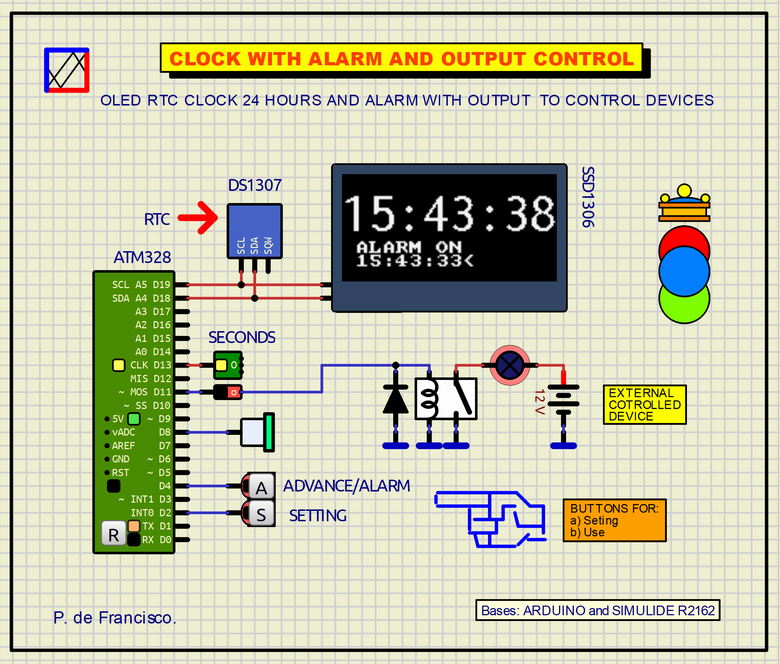
SCHEME:
The scheme is based on the ATM328 controller (Arduino UNO controller), the 128x64 pixel SSD1306 OLED and the RTC (Real Time Clock) as main components. OLED and RTC communicate with the controller via I2C with different addressing (OLED: 60d, 3Ch and RTC: 208d, D0h).
It has three outputs: D13 seconds monitoring output. D11 relay activation output. D8 output to a speaker. As inputs there are the ADVANCE/ALARM buttons on D4 and SETTING on D2. These buttons are active at a HIGH level so in the real circuit they need a 1k resistor connected to ground.
The relay must be 5V and low consumption. Circuits to be controlled upon activation of the alarm can be connected to its contacts, in our example a 12V lamp.
PROGRAM:
The program uses the libraries: U8x8lib.h and RTClib.h, very standard and easy to find and download. Source and executable object are found in the zip file attached to this example.
SUBCIRCUITS:
This example integrates several subcircuits located in the "data" folder into the ZIP attached. This folder must always be next to the "sim1" scheme so that it can be executed. A subcircuit is a “custom” circuit that accumulates a set of Simulide base components (primitive function) to obtain a new or an adapted function. These subcircuits are treated by Simulide as another component of its own structure.
User can create his own subcircuits or use the ones published here in your own designs once the procedure is known, explained in detail in the Simulide tutorials: https://simulide.com/p/subcircuits/
* Communication with the author: Simulide/User/Messages/Defran
P. de Francisco.
Click for thumbs down.0Click for thumbs up.0
Last edited on December 18, 2024, 10:55 pm by Defran