
349__CRYSTAL BALL_TINY84 AND OLED SSD1306.
Quote from Defran on January 18, 2024, 8:22 pm
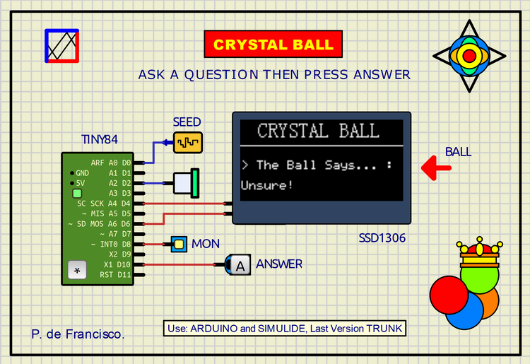
349__CRYSTAL BALL_TINY84-OLED. (Simulide R2162 or higher). For R2162 copy the folder tinyx4 in Simulide/data/AVR.
In the Simulide R2162 version, the possibility of using the SSD1306 OLED screen with the Tiny84 controller has been implemented. This is the first example with these two components.
This example is a fun game of potential prediction of the future based on the "divination power" of the properly interrogated crystal ball. First you are asked to formulate a question on any topic, then you press the [A] Answer button and the ball gives an answer, concrete or confusing, in the style of the fortune tellers of Delphi. This is what fun is all about.
SCHEME:
The scheme is sufficiently self-explanatory, it is based on a tiny84 controller, usable under the Arduino orbit. Connected to it are an I2C OLED (128x64), a speaker, a button, an LED and a random wave generator used as a seed to give greater randomness to the random function of the program.
PROGRAM:
This program requires to be compiled for Tiny84. It can be compiled using the Arduino IDE or using Simulide by adjusting the Compiler Setting: a) board: custom, b) Custom board: ATTinyCore:avr:attinyx4; but for this the folder "ATTinyCore" must exist in the folder of Arduino like this: Arduino/Hardware/ATTinyCore. A Zip file with AttinyCore is attached along with the project Zip.
The C program is found in source and object in the file attached to this example.And do not forget for R2162 copy the folder tinyx4 in Simulide/data/AVR.// CRYSTAL BALL IN TINY84 WITH OLED. DEFRAN24 // Compile in Simulide/Custom/Custom Board: ATTinyCore:avr:attinyx4 #include <TinyWireM.h> // OLED ADDR.: 60d (3Ch) #include <Tiny4kOLED.h> int mon=8; const int pulsa=10; int pito=2; int pulsav=0; int respues; void setup() { oled.begin(128, 64, sizeof(tiny4koled_init_128x64br), tiny4koled_init_128x64br); oled.clear(); oled.on(); pinMode(mon, OUTPUT); digitalWrite(mon,HIGH); digitalWrite(mon,LOW); pinMode(pulsa, INPUT_PULLUP); pinMode(pito, OUTPUT); randomSeed(analogRead(A0)); // SEED } void loop() { oled.setFont(FONT8X16); oled.setCursor(6, 0); oled.print(" CRYSTAL BALL"); oled.setFont(FONT6X8); oled.setCursor(0, 2); oled.fillToEOL(0x10); // LINE oled.setCursor(2, 4); oled.print("> ASK AND PRESS [A]"); tone(pito, 100, 60); // AVZ, FREQ, TIME do {pulsav=digitalRead(pulsa); delay (50);} // PRESS THE BUTTON while (pulsav==HIGH); respues=random(13); oled.setCursor(2, 3); oled.print(" "); oled.setCursor(0, 4); oled.print("> The Ball Says... : "); digitalWrite(mon, HIGH); delay(300); digitalWrite(mon, LOW); delay(300); digitalWrite(mon, HIGH); delay(300); digitalWrite(mon, LOW); delay(300); digitalWrite(mon, HIGH); oled.setCursor(0, 6); switch (respues) { case 0: oled.print("Yes!!"); break; case 1: oled.print("Likely!"); break; case 2: oled.print("THAT'S HOW IT IS!"); break; case 3: oled.print("Very Good!"); break; case 4: oled.print("Unsure!"); break; case 5: oled.print("New Question..."); break; case 6: oled.print("Doubful!"); break; case 7: oled.print("Not!!"); break; case 8: oled.print("Bull Shit!"); break; case 9: oled.print("AY AY AY..."); break; case 10: oled.print("In God's hands"); break; case 11: oled.print("If you believe it"); break; case 12: oled.print("That is secret"); break; } tone(pito, 900, 60); // AVZ, FREQ, TIME delay(4000); digitalWrite(mon, LOW); oled.setCursor(0, 4); oled.print(" "); oled.setCursor(0, 6); oled.print(" "); }
SUBCIRCUITS:
This example integrates several subcircuits located in the "data" folder into the ZIP attached. This folder must always be next to the "sim1" scheme so that it can be executed. A subcircuit is a “custom” circuit that accumulates a set of Simulide base components (primitive function) to obtain a new or an adapted function. These subcircuits are treated by Simulide as another component of its own structure. User can create his own subcircuits or use the ones published here in your own designs once the procedure is known, explained in detail in the Simulide tutorials: https://simulide.com/p/subcircuits/
* Communication with the author: Simulide/User/Messages/Defran
P. de Francisco.
349__CRYSTAL BALL_TINY84-OLED. (Simulide R2162 or higher). For R2162 copy the folder tinyx4 in Simulide/data/AVR.
In the Simulide R2162 version, the possibility of using the SSD1306 OLED screen with the Tiny84 controller has been implemented. This is the first example with these two components.
SCHEME:
PROGRAM:
This program requires to be compiled for Tiny84. It can be compiled using the Arduino IDE or using Simulide by adjusting the Compiler Setting: a) board: custom, b) Custom board: ATTinyCore:avr:attinyx4; but for this the folder "ATTinyCore" must exist in the folder of Arduino like this: Arduino/Hardware/ATTinyCore. A Zip file with AttinyCore is attached along with the project Zip.
// CRYSTAL BALL IN TINY84 WITH OLED. DEFRAN24
// Compile in Simulide/Custom/Custom Board: ATTinyCore:avr:attinyx4

#include <TinyWireM.h>    // OLED ADDR.: 60d (3Ch)
#include <Tiny4kOLED.h>
int mon=8;
const int pulsa=10;
int pito=2;
int pulsav=0;
int respues;

void setup()
{
  oled.begin(128, 64, sizeof(tiny4koled_init_128x64br), tiny4koled_init_128x64br);
  oled.clear();
  oled.on();
  pinMode(mon, OUTPUT);
  digitalWrite(mon,HIGH);
  digitalWrite(mon,LOW);
  pinMode(pulsa, INPUT_PULLUP);
  pinMode(pito, OUTPUT);
  randomSeed(analogRead(A0));                 // SEED
}

void loop()
{
  oled.setFont(FONT8X16);
  oled.setCursor(6, 0);
  oled.print(" CRYSTAL BALL");
  oled.setFont(FONT6X8);
  oled.setCursor(0, 2);
  oled.fillToEOL(0x10);                       // LINE
  oled.setCursor(2, 4);
  oled.print("> ASK AND PRESS [A]");
  tone(pito, 100, 60);                        // AVZ, FREQ, TIME
  do {pulsav=digitalRead(pulsa); delay (50);} // PRESS THE BUTTON
  while (pulsav==HIGH);
  respues=random(13);
  oled.setCursor(2, 3);
  oled.print("                       ");
  oled.setCursor(0, 4);
  oled.print("> The Ball Says... : ");
  digitalWrite(mon, HIGH); delay(300); digitalWrite(mon, LOW); delay(300);
  digitalWrite(mon, HIGH); delay(300); digitalWrite(mon, LOW); delay(300);
  digitalWrite(mon, HIGH);
  oled.setCursor(0, 6);
  switch (respues)
  {
    case 0: oled.print("Yes!!");              break;
    case 1: oled.print("Likely!");            break;
    case 2: oled.print("THAT'S HOW IT IS!");  break;
    case 3: oled.print("Very Good!");         break;
    case 4: oled.print("Unsure!");            break;
    case 5: oled.print("New Question...");    break;
    case 6: oled.print("Doubful!");           break;
    case 7: oled.print("Not!!");              break;
    case 8: oled.print("Bull Shit!");         break;
    case 9: oled.print("AY AY AY...");        break;
    case 10: oled.print("In God's hands");    break;
    case 11: oled.print("If you believe it"); break;
    case 12: oled.print("That is secret");    break;
  }
  tone(pito, 900, 60);                     // AVZ, FREQ, TIME
  delay(4000);
  digitalWrite(mon, LOW);
  oled.setCursor(0, 4);
  oled.print("                     ");
  oled.setCursor(0, 6);
  oled.print("                     ");
}
SUBCIRCUITS:
This example integrates several subcircuits located in the "data" folder into the ZIP attached. This folder must always be next to the "sim1" scheme so that it can be executed. A subcircuit is a “custom” circuit that accumulates a set of Simulide base components (primitive function) to obtain a new or an adapted function. These subcircuits are treated by Simulide as another component of its own structure. User can create his own subcircuits or use the ones published here in your own designs once the procedure is known, explained in detail in the Simulide tutorials: https://simulide.com/p/subcircuits/
* Communication with the author: Simulide/User/Messages/Defran
P. de Francisco.
Uploaded files: