
347__MANUAL COUNTER_TINY85 AND OLED SSD1306
Quote from Defran on January 16, 2024, 12:39 am
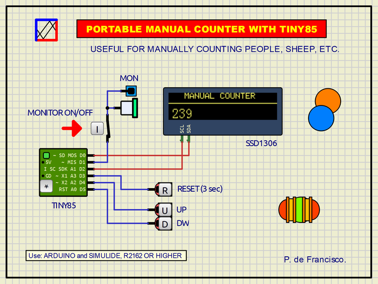
347__MANUAL COUNTER_TINY85 AND OLED SSD1306. (Simulide R2194 or higher).
In the Simulide R2162 version, the possibility of using the SSD1306 OLED screen with the Tiny85 controller has been implemented. This is the first example with these two components.
This example consists of a Portable Manual Counter governed by three buttons: UP, DOWN and RESET. These perform the functions of their title, which are instantaneous except for RESET which needs to be pressed for three seconds to delete. These three buttons are monitored by an LED and by short beeps of different frequencies. A switch (closed by default) has been added to avoid potential annoyances.
SCHEME:
It is based on the aforementioned components. The Tiny85, despite its smallness, gives immense potential for making projects with little space, so its association with the OLED was essential due to the I2C bus.
PROGRAM:
This program requires to be compiled for Tiny85. It can be compiled using the Arduino IDE or using Simulide by adjusting the Compiler Setting: a) board: custom, b) Custom board: ATTinyCore:avr:attinyx5; but for this the folder "ATTinyCore" must exist in the folder of Arduino like this: Arduino/Hardware/ATTinyCore. A Zip file with AttinyCore is attached along with the project Zip.
// MANUAL COUNTER WITH TINY85 AND OLED SSD1306. DEFRAN24
// OLED ADDR.: 60 (3C)
// Compile in Custom: ATTinyCore:avr:attinyx5

#include <TinyWireM.h>   // I2C FOR TINY85.
#include <Tiny4kOLED.h>  // GRAPHICS AND TEXTS.
int conta=0;
int mon=1;
int up=4;
int dw=5;
int rst=3;
int dat;
int upv;
int dwv;
int rstv;
int rstd;
long tim;
int pit;

void setup()
{
  oled.begin(128, 32, sizeof(tiny4koled_init_128x32), tiny4koled_init_128x32);
  oled.clear();
  oled.on();
  oled.setCursor(0, 0);
  oled.setFont(FONT6X8);
  oled.print("   MANUAL COUNTER");
  oled.setCursor(0, 1);
  oled.fillToEOL(0x10);           // LINE
  oled.setCursor(4, 2);
  oled.setFont(FONT8X16);
  oled.setCursor(4,2);
  oled.print("0");
  pinMode(mon, OUTPUT);
  pinMode(up, INPUT_PULLUP);
  pinMode(dw, INPUT_PULLUP);
  pinMode(rst, INPUT_PULLUP);
}

void loop()
{
  dat=digitalRead(up); if(dat!=upv) {if(dat==HIGH) conta++; deta();} pit=800;  pito(); upv=dat;
  dat=digitalRead(dw); if(dat!=dwv) {if(dat==HIGH) conta--; deta();} pit=1200; pito(); dwv=dat;
  if(digitalRead(rst)==HIGH) tim++;
  if(tim==9000) {rstd=4; deta();}
}

void deta()
{
  if (conta<0 || rstd==4) {conta=0; rstd=0;}
  oled.setCursor(4, 2);
  oled.print("               ");
  oled.setCursor(4, 2);
  oled.print(conta);
  tim=0;
}

void pito()
{
  tone(mon, pit, 60); // PORT, NOTE, TIME.
}
SUBCIRCUITS:
This example integrates several subcircuits located in the "data" folder into the ZIP attached. This folder must always be next to the "sim1" scheme so that it can be executed. A subcircuit is a “custom” circuit that accumulates a set of Simulide base components (primitive function) to obtain a new or an adapted function. These subcircuits are treated by Simulide as another component of its own structure. User can create his own subcircuits or use the ones published here in your own designs once the procedure is known, explained in detail in the Simulide tutorials: https://simulide.com/p/subcircuits/
* Communication with the author: Simulide/User/Messages/Defran
P. de Francisco.
Uploaded files: