
346__ SLIDER ANALOG SWITCH CONTOLLING A ASCII 7X5 LED MATRIX
Quote from Defran on January 13, 2024, 1:34 pm
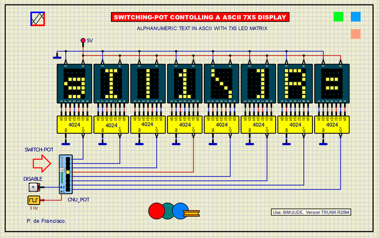
346_SLIDER ANALOG SWITCH CONTOLLING A ASCII 7X5 LED MATRIX. (Simulide R2116 or higher.)
In this example we intend to manage an eight-digit display. Each digit is a 7x5 LED matrix, a typical matrix for the presentation of all ASCII characters. Each digit is controlled by a 7-bit binary counter (Cmos 4024). The corresponding pulses are applied to the clock input to reach the character to be presented.
The clock inputs of the 8 counters are selected by the switch that we have called Switch-pot. The scan rate is 3 Hz and a switch applied to "D" (Disable) can stop passing pulses to the selected counter. To enter the full text you must access all the digits in the same way.
SCHEME:
The electrical diagram is based on two subcircuits: The 7X5 single-digit LED display and the eight-position analog slider switch.
7x5 Display:
Five ROM memories (corresponding to the columns) in whose eight outputs there are separate strings of LEDs that correspond to the rows. Each of the ROMs contain in hexadecimal the corresponding data to dynamically form the ASCII character selected by the address bus (A0 to A6), this bus is formed in hexadecimal from the inputs A to G of the display. This is achieved through adders and LatchD. The "H" input is used to work in hexadecimal or in ASCII addressing. The "S" input saves the address in the Latch or bypass.
Analog Slider Switch:
Internal diagram of the analog slider switch (Made of Simulide primitive functions):
a) ADC: 3-bit digital analog converter from the analog level to its output.
b) DECODER 3 TO 8 to show the position of the cursor on LED.
c) MUX: 3-bit analog multiplexer input of the internal ADC bus. This MUX one has a disable input.
SUBCIRCUITS:
This example integrates several subcircuits located in the "data" folder into the ZIP attached. This folder must always be next to the "sim1" scheme so that it can be executed. A subcircuit is a “custom” circuit that accumulates a set of Simulide base components (primitive function) to obtain a new or an adapted function. These subcircuits are treated by Simulide as another component of its own structure. User can create his own subcircuits or use the ones published here in your own designs once the procedure is known, explained in detail in the Simulide tutorials: https://simulide.com/p/subcircuits/
* Communication with the author: Simulide/User/Messages/Defran
P. de Francisco.
346_SLIDER ANALOG SWITCH CONTOLLING A ASCII 7X5 LED MATRIX. (Simulide R2116 or higher.)
In this example we intend to manage an eight-digit display. Each digit is a 7x5 LED matrix, a typical matrix for the presentation of all ASCII characters. Each digit is controlled by a 7-bit binary counter (Cmos 4024). The corresponding pulses are applied to the clock input to reach the character to be presented.
The clock inputs of the 8 counters are selected by the switch that we have called Switch-pot. The scan rate is 3 Hz and a switch applied to "D" (Disable) can stop passing pulses to the selected counter. To enter the full text you must access all the digits in the same way.
SCHEME:
The electrical diagram is based on two subcircuits: The 7X5 single-digit LED display and the eight-position analog slider switch.
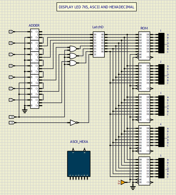
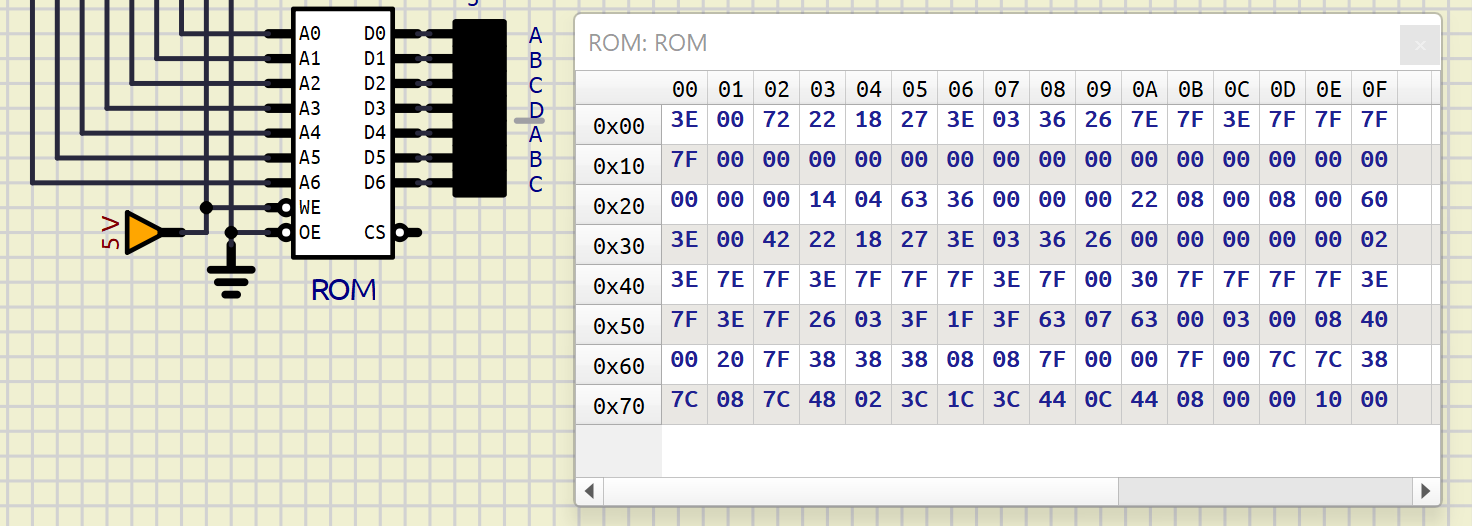
7x5 Display:
Five ROM memories (corresponding to the columns) in whose eight outputs there are separate strings of LEDs that correspond to the rows. Each of the ROMs contain in hexadecimal the corresponding data to dynamically form the ASCII character selected by the address bus (A0 to A6), this bus is formed in hexadecimal from the inputs A to G of the display. This is achieved through adders and LatchD. The "H" input is used to work in hexadecimal or in ASCII addressing. The "S" input saves the address in the Latch or bypass.
Analog Slider Switch:
Internal diagram of the analog slider switch (Made of Simulide primitive functions):
a) ADC: 3-bit digital analog converter from the analog level to its output.
b) DECODER 3 TO 8 to show the position of the cursor on LED.
c) MUX: 3-bit analog multiplexer input of the internal ADC bus. This MUX one has a disable input.

SUBCIRCUITS:
This example integrates several subcircuits located in the "data" folder into the ZIP attached. This folder must always be next to the "sim1" scheme so that it can be executed. A subcircuit is a “custom” circuit that accumulates a set of Simulide base components (primitive function) to obtain a new or an adapted function. These subcircuits are treated by Simulide as another component of its own structure. User can create his own subcircuits or use the ones published here in your own designs once the procedure is known, explained in detail in the Simulide tutorials: https://simulide.com/p/subcircuits/
* Communication with the author: Simulide/User/Messages/Defran
P. de Francisco.
Uploaded files: