341__WINDING MACHINE B.
Quote from Defran on December 31, 2023, 12:30 pm
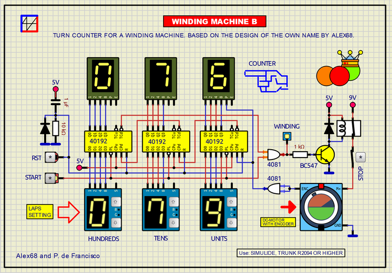
341_WINDING MACHINE B. (SIMULIDE R2094 or higher. Example Based on the same name of the user Alex68).
Three CMOS UP/DOWN BCD counters with 4 presettable bits each count (in down mode) the pulses that arrive from the DC-MOTOR ENCODER. Each pulse is one turn and can count up to 1000. The preselection is done with three rotary switches with BCD output. The LED display is made up of three individual BCD input digits with decimal point. The reset is controlled by a button and a cell RC for reset at boot. The diode produces instantaneous discharge of the capacitor after shutdown. The output of the counters is applied to an OR gate combined with the Start switch, at the gate output a transistor acts as inverter and driver to activate the relay that powers the motor.
CONTROLS:
a) RST: To reset the counter manually.
b) START: To start or stop the counter. In OFF you can change the preset value. In ON the counter starts decreasing until 0 when it stops, the relay is deactivated and the motor is disconnected.
c) STOP: Emergency switch.SUBCIRCUITS:
This example integrates several subcircuits located in the "data" folder into the ZIP attached. This folder must always be next to the "sim1" scheme so that it can be executed. A subcircuit is a “custom” circuit that accumulates a set of Simulide base components (primitive function) to obtain a new or an adapted function. These subcircuits are treated by Simulide as another component of its own structure. User can create his own subcircuits or use the ones published here in your own designs once the procedure is known, explained in detail in the Simulide tutorials: https://simulide.com/p/subcircuits/
* Communication with the author: Simulide/User/Messages/Defran
P. de Francisco.

341_WINDING MACHINE B. (SIMULIDE R2094 or higher. Example Based on the same name of the user Alex68).
Three CMOS UP/DOWN BCD counters with 4 presettable bits each count (in down mode) the pulses that arrive from the DC-MOTOR ENCODER. Each pulse is one turn and can count up to 1000. The preselection is done with three rotary switches with BCD output. The LED display is made up of three individual BCD input digits with decimal point. The reset is controlled by a button and a cell RC for reset at boot. The diode produces instantaneous discharge of the capacitor after shutdown. The output of the counters is applied to an OR gate combined with the Start switch, at the gate output a transistor acts as inverter and driver to activate the relay that powers the motor.
CONTROLS:
a) RST: To reset the counter manually.
b) START: To start or stop the counter. In OFF you can change the preset value. In ON the counter starts decreasing until 0 when it stops, the relay is deactivated and the motor is disconnected.
c) STOP: Emergency switch.
SUBCIRCUITS:
This example integrates several subcircuits located in the "data" folder into the ZIP attached. This folder must always be next to the "sim1" scheme so that it can be executed. A subcircuit is a “custom” circuit that accumulates a set of Simulide base components (primitive function) to obtain a new or an adapted function. These subcircuits are treated by Simulide as another component of its own structure. User can create his own subcircuits or use the ones published here in your own designs once the procedure is known, explained in detail in the Simulide tutorials: https://simulide.com/p/subcircuits/
* Communication with the author: Simulide/User/Messages/Defran
P. de Francisco.
Uploaded files: