
338__ELECTRONIC RHEOSTAT
Quote from Defran on December 17, 2023, 9:25 am
338_ELECTRONIC RHEOSTAT (Simulide R2116 or higher.)
A RHEOSTAT is an alternating current voltage regulator with electro-mechanical components (Cursors, Windings, etc.). Here the aim is to obtain a rheostat with electronic components to optimize space and handling, simulating it with Simulide.
SCHEME:
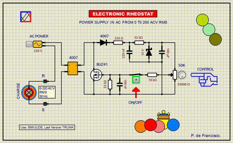
The application circuit is composed of three parts in series: 1) 220 ACV power input, 2) lamp as electrical load and 3) a diode bridge in whose POSITIVE and NEGATIVE outputs the load regulation will be applied by the BUZ41 power MOS. The gate of this MOS is controlled by a potentiometer that will act as a rheostat regulator. In between there is a switch that connects or cuts off the power to the external load (lamp). The regulation voltage itself is obtained from the output of the diode bridge, rectified, filtered and stabilized by a zener, without the need for any additional DC power supply.
Use: close the "ON/OFF" switch, then act on the control potentiometer so that the lamp will vary its luminosity.
SUBCIRCUITS:
This example integrates several subcircuits located in the "data" folder into the ZIP attached. This folder must always be next to the "sim1" scheme so that it can be executed. A subcircuit is a "custom" circuit that accumulates a set of Simulide base components (primitive function) to obtain a new or an adapted function. These subcircuits are treated by Simulide as another component of its own structure. User can create his own subcircuits or use the ones published here in your own designs once the procedure is known, explained in detail in the Simulide tutorials: https://simulide.com/p/subcircuits/
* Communication with the author: Simulide/User/Messages/Defran
P. de Francisco.
338_ELECTRONIC RHEOSTAT (Simulide R2116 or higher.)
A RHEOSTAT is an alternating current voltage regulator with electro-mechanical components (Cursors, Windings, etc.). Here the aim is to obtain a rheostat with electronic components to optimize space and handling, simulating it with Simulide.
SCHEME:
The application circuit is composed of three parts in series: 1) 220 ACV power input, 2) lamp as electrical load and 3) a diode bridge in whose POSITIVE and NEGATIVE outputs the load regulation will be applied by the BUZ41 power MOS. The gate of this MOS is controlled by a potentiometer that will act as a rheostat regulator. In between there is a switch that connects or cuts off the power to the external load (lamp). The regulation voltage itself is obtained from the output of the diode bridge, rectified, filtered and stabilized by a zener, without the need for any additional DC power supply.
Use: close the "ON/OFF" switch, then act on the control potentiometer so that the lamp will vary its luminosity.
SUBCIRCUITS:
This example integrates several subcircuits located in the "data" folder into the ZIP attached. This folder must always be next to the "sim1" scheme so that it can be executed. A subcircuit is a "custom" circuit that accumulates a set of Simulide base components (primitive function) to obtain a new or an adapted function. These subcircuits are treated by Simulide as another component of its own structure. User can create his own subcircuits or use the ones published here in your own designs once the procedure is known, explained in detail in the Simulide tutorials: https://simulide.com/p/subcircuits/
* Communication with the author: Simulide/User/Messages/Defran
P. de Francisco.
Uploaded files: