
337__MOS IN SWITCHING MODE
Quote from Defran on December 14, 2023, 2:07 pm
337_MOS IN SWITCHING MODE (Simulide R2116 or higher.)
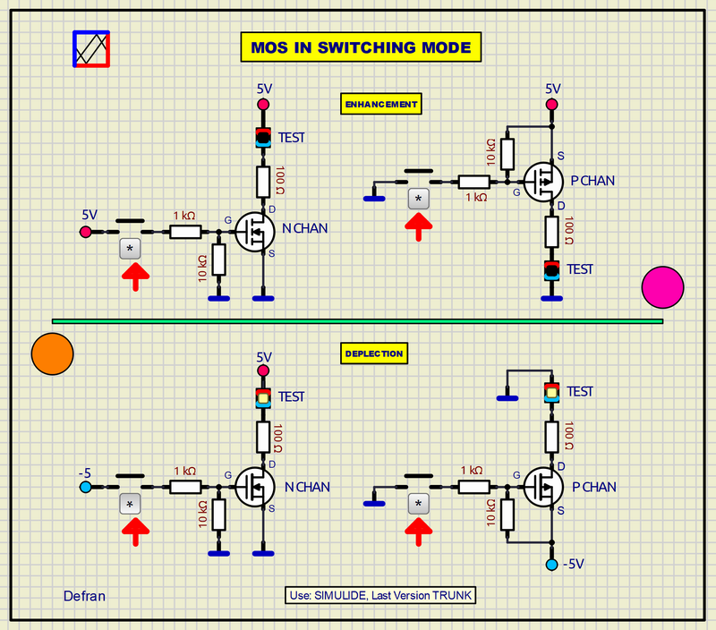
The use and polarization of the four MOS cases of ENHANCEMENT and DEPLECTION in switching, N channel and P channel are shown here. The diagrams are sufficiently explanatory. Each MOS is controlled by a push button and the operating status is displayed on an LED.
SCHEME:
a).- ENHANCEMENT, N Channel. At rest the MOS does not conduct. When you press the button, the GATE is polarized with 5V, the MOS conducts and the LED connected to the drain lights UP.
b).- ENHANCEMENT, P Channel. At rest the MOS does not conduct. When you press the button, the GATE is polarized with GND, the MOS conducts and the LED connected to the drain lights UP.
c).- DEPLECTION, N Channel. At rest the MOS conducts. When you press the button, the GATE is polarized with -5V, the MOS is cut off and the LED connected to the drain turns OFF.
d).- DEPLECTION, P Channel. At rest the MOS conducts. When you press the button, the GATE is polarized with GND, the MOS conducts and the LED connected to the drain turns OFF.
SUBCIRCUITS:
This example integrates several subcircuits located in the "data" folder into the ZIP attached. This folder must always be next to the "sim1" scheme so that it can be executed. A subcircuit is a "custom" circuit that accumulates a set of Simulide base components (primitive function) to obtain a new or an adapted function. These subcircuits are treated by Simulide as another component of its own structure. User can create his own subcircuits or use the ones published here in your own designs once the procedure is known, explained in detail in the Simulide tutorials: https://simulide.com/p/subcircuits/
* Communication with the author: Simulide/User/Messages/Defran
P. de Francisco.
337_MOS IN SWITCHING MODE (Simulide R2116 or higher.)
The use and polarization of the four MOS cases of ENHANCEMENT and DEPLECTION in switching, N channel and P channel are shown here. The diagrams are sufficiently explanatory. Each MOS is controlled by a push button and the operating status is displayed on an LED.
SCHEME:
a).- ENHANCEMENT, N Channel. At rest the MOS does not conduct. When you press the button, the GATE is polarized with 5V, the MOS conducts and the LED connected to the drain lights UP.
b).- ENHANCEMENT, P Channel. At rest the MOS does not conduct. When you press the button, the GATE is polarized with GND, the MOS conducts and the LED connected to the drain lights UP.
c).- DEPLECTION, N Channel. At rest the MOS conducts. When you press the button, the GATE is polarized with -5V, the MOS is cut off and the LED connected to the drain turns OFF.
d).- DEPLECTION, P Channel. At rest the MOS conducts. When you press the button, the GATE is polarized with GND, the MOS conducts and the LED connected to the drain turns OFF.
SUBCIRCUITS:
This example integrates several subcircuits located in the "data" folder into the ZIP attached. This folder must always be next to the "sim1" scheme so that it can be executed. A subcircuit is a "custom" circuit that accumulates a set of Simulide base components (primitive function) to obtain a new or an adapted function. These subcircuits are treated by Simulide as another component of its own structure. User can create his own subcircuits or use the ones published here in your own designs once the procedure is known, explained in detail in the Simulide tutorials: https://simulide.com/p/subcircuits/
* Communication with the author: Simulide/User/Messages/Defran
P. de Francisco.
Uploaded files: