
334__DTMF_PHONE TONES
Quote from Defran on December 3, 2023, 9:05 pm
334_DTMF_PHONE TONES. (Simulide R2116 or higher.)
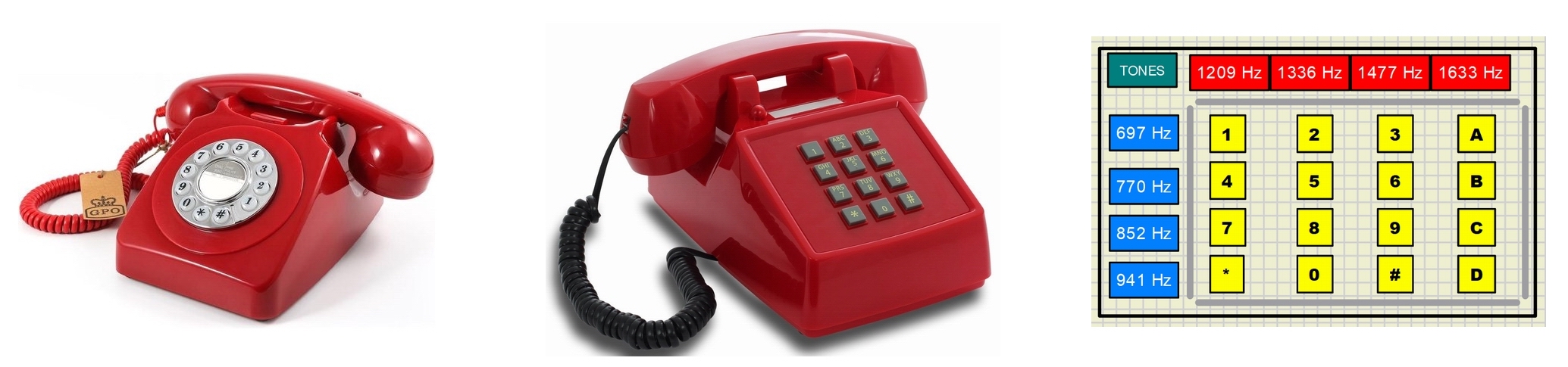
The first telephones had a rotating number dialing wheel, which sent the pulses of each dialed number to the Telephone Exchange. This was a very slow procedure, so to improve this in 1963 Western Electric began to manufacture faster and more comfortable keyboard telephones. The keypad was based on sending an audible dial tone for each number. This system still exists as a standard.
The tones are not a single frequency but a combination of two for better transmission and decoding. In the images you can see the frequency indicators that correspond to each key.
In this example we are going to do a simulation of this tone dialing system called DTMF (Dual Tone Multi-Frequency).
To know more: https://en.wikipedia.org/wiki/Dual-tone_multi-frequency_signaling
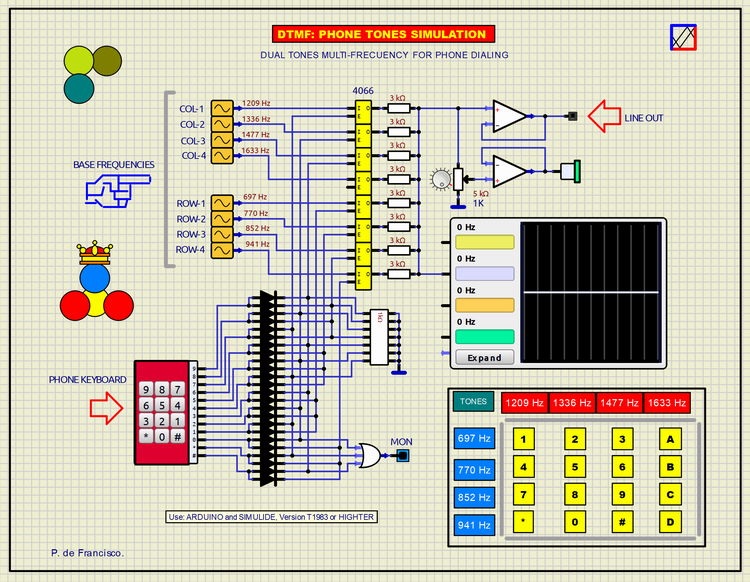
SCHEME:
In our scheme there are eight generators of the standard base tones that are added two by two by opening eight analog switches. The sum of the waves is done through a resistive network at their output. The signal goes to an audio amplifier to hear it and to an opamp with a free-use output.
A standard keyboard (7 keys in our example) addresses a ROM memory according to the number pressed. The output of the ROM opens the corresponding analog switches already mentioned. Writing, reading and editing the ROM can be done by clicking on the ROM with the right mouse button. The attached zip includes a file with its contents in hexadecimal.
Secondly, other scheme has been included with a diode-based decoder so that pressing a number opens its corresponding analog switches. For example, if a 9 is pressed, a HIGH level is sent to the "E" inputs of the frequency switches: 1477 and 852.
Play by pressing different keys, observe the composed waves on the oscilloscope and listen to the tone that will surely be recognizable.
SUBCIRCUITS:
This example integrates several subcircuits located in the "data" folder into the ZIP attached. This folder must always be next to the "sim1" scheme so that it can be executed. A subcircuit is a "custom" circuit that accumulates a set of Simulide base components (primitive function) to obtain a new or an adapted function. These subcircuits are treated by Simulide as another component of its own structure. User can create his own subcircuits or use the ones published here in your own designs once the procedure is known, explained in detail in the Simulide tutorials: https://simulide.com/p/subcircuits/
* Communication with the author: Simulide/User/Messages/Defran
P. de Francisco.


334_DTMF_PHONE TONES. (Simulide R2116 or higher.)
The first telephones had a rotating number dialing wheel, which sent the pulses of each dialed number to the Telephone Exchange. This was a very slow procedure, so to improve this in 1963 Western Electric began to manufacture faster and more comfortable keyboard telephones. The keypad was based on sending an audible dial tone for each number. This system still exists as a standard.
The tones are not a single frequency but a combination of two for better transmission and decoding. In the images you can see the frequency indicators that correspond to each key.
In this example we are going to do a simulation of this tone dialing system called DTMF (Dual Tone Multi-Frequency).

To know more: https://en.wikipedia.org/wiki/Dual-tone_multi-frequency_signaling
SCHEME:
In our scheme there are eight generators of the standard base tones that are added two by two by opening eight analog switches. The sum of the waves is done through a resistive network at their output. The signal goes to an audio amplifier to hear it and to an opamp with a free-use output.
A standard keyboard (7 keys in our example) addresses a ROM memory according to the number pressed. The output of the ROM opens the corresponding analog switches already mentioned. Writing, reading and editing the ROM can be done by clicking on the ROM with the right mouse button. The attached zip includes a file with its contents in hexadecimal.
Secondly, other scheme has been included with a diode-based decoder so that pressing a number opens its corresponding analog switches. For example, if a 9 is pressed, a HIGH level is sent to the "E" inputs of the frequency switches: 1477 and 852.
Play by pressing different keys, observe the composed waves on the oscilloscope and listen to the tone that will surely be recognizable.
SUBCIRCUITS:
This example integrates several subcircuits located in the "data" folder into the ZIP attached. This folder must always be next to the "sim1" scheme so that it can be executed. A subcircuit is a "custom" circuit that accumulates a set of Simulide base components (primitive function) to obtain a new or an adapted function. These subcircuits are treated by Simulide as another component of its own structure. User can create his own subcircuits or use the ones published here in your own designs once the procedure is known, explained in detail in the Simulide tutorials: https://simulide.com/p/subcircuits/
* Communication with the author: Simulide/User/Messages/Defran
P. de Francisco.
Uploaded files: