333__UJT_UNIJUNCTION TRANSISTOR
Quote from Defran on December 2, 2023, 9:57 pm
333_UJT_UNIJUNCTION TRANSISTOR. (Simulide R2116 or higher.)
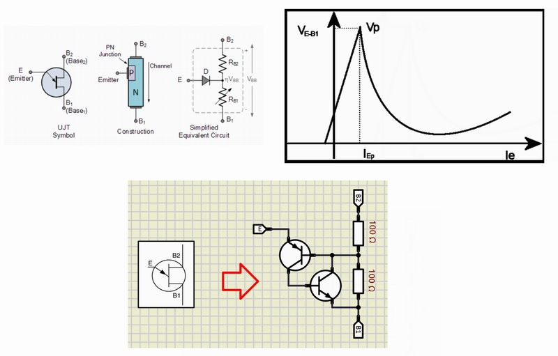
This is a small study and simulation of the UNIJUNCTION or UJT transistor. The UJT is a single PN or NP junction single transistor. It was discovered around 1953 and its use is mainly as an oscillator due to its negative resistance behavior when the emitter voltage increases. Secondly, several graphs show what has been discussed. To know more: https://www.electronics-tutorials.ws/power/unijunction-transistor.htmlSCHEME:
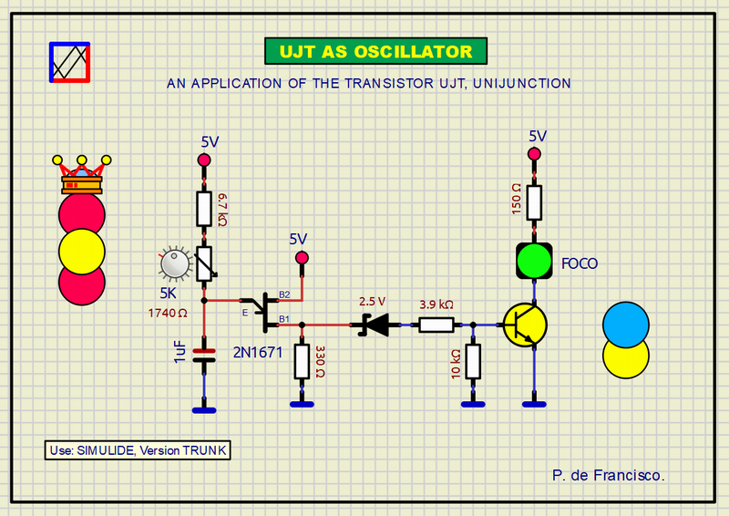
This scheme is based on the simulation of a UJT (here done in a subcircuit) to obtain an oscillator using the real typical circuit of this function. The signal is taken from B1, it is weak and with a DC component, Therefore, for its application it must be amplified prior to the elimination of the continuous component using a zener. At the output, an LED shows the flashing signal after a short time after connection.
SUBCIRCUITS:
This example integrates several subcircuits located in the "data" folder into the ZIP attached. This folder must always be next to the "sim1" scheme so that it can be executed. A subcircuit is a "custom" circuit that accumulates a set of Simulide base components (primitive function) to obtain a new or an adapted function. These subcircuits are treated by Simulide as another component of its own structure. User can create his own subcircuits or use the ones published here in your own designs once the procedure is known, explained in detail in the Simulide tutorials: https://simulide.com/p/subcircuits/
* Communication with the author: Simulide/User/Messages/Defran
P. de Francisco.

333_UJT_UNIJUNCTION TRANSISTOR. (Simulide R2116 or higher.)

SCHEME:
This scheme is based on the simulation of a UJT (here done in a subcircuit) to obtain an oscillator using the real typical circuit of this function. The signal is taken from B1, it is weak and with a DC component, Therefore, for its application it must be amplified prior to the elimination of the continuous component using a zener. At the output, an LED shows the flashing signal after a short time after connection.
SUBCIRCUITS:
This example integrates several subcircuits located in the "data" folder into the ZIP attached. This folder must always be next to the "sim1" scheme so that it can be executed. A subcircuit is a "custom" circuit that accumulates a set of Simulide base components (primitive function) to obtain a new or an adapted function. These subcircuits are treated by Simulide as another component of its own structure. User can create his own subcircuits or use the ones published here in your own designs once the procedure is known, explained in detail in the Simulide tutorials: https://simulide.com/p/subcircuits/
* Communication with the author: Simulide/User/Messages/Defran
P. de Francisco.
Uploaded files: