
329__SERVO_RANDOM
Quote from Defran on November 30, 2023, 2:22 pm
329_SERVO_RANDOM. (Simulide R2116 or higher.)
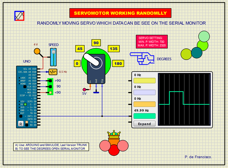
This example is based on moving the rotor of a SERVO-MOTOR randomly from 0 to 180 degrees. This creates a dynamic eclipsing effect applicable in different exercises to provide a certain aesthetic.A SERVO-MOTOR moves its rotor in degrees up to 180. To do this, pulses of 1 to 2 ms must be applied with a frequency of 50Hz (CYCLE=20ms). 1 ms corresponds to zero degrees and 2 ms to 180.
SCHEME:
This scheme is based on the Arduino UNO to which the SERVO is connected via D3. A 0 to 5v power source is connected to A5 to regulate the rotation speed of the rotor. LEDs are connected to D11, D13 and D15 to indicate the rotation areas of the rotor: <90 degrees, 90 degrees as the center point and >90 degrees. A low-frequency random oscillator is connected to A4, which acts as a seed of the program to increase the randomness cycle. When the program starts, the random movement will begin indefinitely. On the oscilloscope the width of the pulse applied to the motor is graphically displayed at all times.
PROGRAM:
The program has been made in Arduino C with the library Servo.h.
// SERVOMOTOR RANDOM. DEFRAN23
// BASES: ARDUINO AND SIMULIDE TRUNK.

#include <Servo.h>
Servo servoRND;               // SERVO NAME
int pos=0;
int sup=15;
int mon=13;
int inf=11;
int step;
int pote;
int speed=90;

void setup()
{
  servoRND.attach(3);
  pinMode(mon, OUTPUT);
  pinMode(sup, OUTPUT);
  pinMode(inf, OUTPUT);
  randomSeed(analogRead(A5));
  Serial.begin(9600);
}

void loop()
{
  step=random(0, 180);           // RANDOM
  Serial.println(step);
  if (step>90) digitalWrite(sup,HIGH); else digitalWrite(sup,LOW);
  if (step>85 && step<95) digitalWrite(mon,HIGH); else digitalWrite(mon,LOW);
  if (step<90) digitalWrite(inf,HIGH); else digitalWrite(inf,LOW);
  servoRND.write(step);           // SERVO
  pote=analogRead(A5);
  speed=map(pote, 0, 1023, 100, 800);
  delay(speed);
}
SUBCIRCUITS:
This example integrates several subcircuits located in the "data" folder into the ZIP attached. This folder must always be next to the "sim1" scheme so that it can be executed. A subcircuit is a "custom" circuit that accumulates a set of Simulide base components (primitive function) to obtain a new or an adapted function. These subcircuits are treated by Simulide as another component of its own structure. User can create his own subcircuits or use the ones published here in your own designs once the procedure is known, explained in detail in the Simulide tutorials: https://simulide.com/p/subcircuits/
* Communication with the author: Simulide/User/Messages/Defran
P. de Francisco.
329_SERVO_RANDOM. (Simulide R2116 or higher.)

SCHEME:
This scheme is based on the Arduino UNO to which the SERVO is connected via D3. A 0 to 5v power source is connected to A5 to regulate the rotation speed of the rotor. LEDs are connected to D11, D13 and D15 to indicate the rotation areas of the rotor: <90 degrees, 90 degrees as the center point and >90 degrees. A low-frequency random oscillator is connected to A4, which acts as a seed of the program to increase the randomness cycle. When the program starts, the random movement will begin indefinitely. On the oscilloscope the width of the pulse applied to the motor is graphically displayed at all times.
PROGRAM:
The program has been made in Arduino C with the library Servo.h.
// SERVOMOTOR RANDOM. DEFRAN23
// BASES: ARDUINO AND SIMULIDE TRUNK.

#include <Servo.h>
Servo servoRND;               // SERVO NAME
int pos=0;
int sup=15;
int mon=13;
int inf=11;
int step;
int pote;
int speed=90;

void setup()
{
  servoRND.attach(3);
  pinMode(mon, OUTPUT);
  pinMode(sup, OUTPUT);
  pinMode(inf, OUTPUT);
  randomSeed(analogRead(A5));
  Serial.begin(9600);
}

void loop()
{
  step=random(0, 180);           // RANDOM
  Serial.println(step);
  if (step>90) digitalWrite(sup,HIGH); else digitalWrite(sup,LOW);
  if (step>85 && step<95) digitalWrite(mon,HIGH); else digitalWrite(mon,LOW);
  if (step<90) digitalWrite(inf,HIGH); else digitalWrite(inf,LOW);
  servoRND.write(step);           // SERVO
  pote=analogRead(A5);
  speed=map(pote, 0, 1023, 100, 800);
  delay(speed);
}
SUBCIRCUITS:
This example integrates several subcircuits located in the "data" folder into the ZIP attached. This folder must always be next to the "sim1" scheme so that it can be executed. A subcircuit is a "custom" circuit that accumulates a set of Simulide base components (primitive function) to obtain a new or an adapted function. These subcircuits are treated by Simulide as another component of its own structure. User can create his own subcircuits or use the ones published here in your own designs once the procedure is known, explained in detail in the Simulide tutorials: https://simulide.com/p/subcircuits/
* Communication with the author: Simulide/User/Messages/Defran
P. de Francisco.
Uploaded files: