
Forum breadcrumbs - You are here:ForumGeneral: Circuits and examples made in SimulIDE344__OHMETER_USE
You need to log in to create posts and topics.
344__OHMETER_USE
Defran@defran
125 Posts
#1 · January 7, 2024, 11:28 am
Quote from Defran on January 7, 2024, 11:28 am
344_OHMETER_USE (Simulide R2094 or higher.)This ohmmeter is a subcircuit capable of making pure ohmic resistance measurements in circuits without any type of power that disturbs the measurement (as is done in reality).The ohmmeter has two inputs: IN and 5V. Apply these as probes at the two resistive measurement points. The value in ohms or kilohms will appear on the OLED screen. The ohmmeter is autoranging. Calibration is obtained by adjusting the screen potentiometer knob. For more precision or other ranges, by clicking with the right mouse button you can access to modify the value of the potentiometer (VarResistor) or its resistance (Resistor) in serial.In the diagram, as a test and measurement example, there is an analog selector with which you can switch to several fixed resistors and a potentiometre.SCHEME:The heart of the schematic is the ohmmeter subcircuit based on the ATmega328 Controller. It has three entrances:IN: Sensitive input.5V: Connected to +5v inside the subcircuit (Do not short circuit GND or connect to another voltage.R: External point to adjust or control the calibration.The subcircuit diagram is very simple and sufficiently self-explanatory. Add that the controller needs an object program (OHMETERH.hex) that by default is loaded in the controller and must always be loaded for it to work. The components in yellow are "exposer", a characteristic that has been attributed to them so that they can be modified from the outside as mentioned.PROGRAM:The program source is included in the subcircuit folder and is the same as other examples already published about this ohmmeter.// OHMETER. DEFRAN23 // BASES: ARDUINO AND SIMULIDE TRUNK. #include <Wire.h> #include <Adafruit_GFX.h> #include <Adafruit_SSD1306.h> #define SCREEN_WIDTH 128 #define SCREEN_HEIGHT 32 #define OLED_RESET 4 // 4: Reset pin, 1 Arduino reset pin. Adafruit_SSD1306 display(SCREEN_WIDTH, SCREEN_HEIGHT, &Wire, OLED_RESET); float Rcal=1000; float Rsample, Vana=0; void setup() { display.begin(SSD1306_SWITCHCAPVCC, 0x3C); // Address 0x3C (60 DECIMAL) display.display(); display.clearDisplay(); } void loop() { int n=analogRead(A0); Vana=map(n, 0,1024, 0,5000)/1000.0; Rsample=(Rcal*(5.0-Vana))/Vana; display.clearDisplay(); display.setTextSize(2); display.setTextColor(WHITE); display.setCursor(4, 0); // x,y if (Rsample>1000) { Rsample=Rsample/1000.0; display.print(Rsample); display.setCursor(4, 18); display.print("Kohms"); } else { display.print(Rsample); display.setCursor(4, 18); display.print("Ohms"); } display.display(); delay(100); }SUBCIRCUITS:This example integrates several subcircuits located in the "data" folder into the ZIP attached. This folder must always be next to the "sim1" scheme so that it can be executed. A subcircuit is a “custom” circuit that accumulates a set of Simulide base components (primitive function) to obtain a new or an adapted function. These subcircuits are treated by Simulide as another component of its own structure. User can create his own subcircuits or use the ones published here in your own designs once the procedure is known, explained in detail in the Simulide tutorials: https://simulide.com/p/subcircuits/* Communication with the author: Simulide/User/Messages/DefranP. de Francisco.

344_OHMETER_USE (Simulide R2094 or higher.)
This ohmmeter is a subcircuit capable of making pure ohmic resistance measurements in circuits without any type of power that disturbs the measurement (as is done in reality).
The ohmmeter has two inputs: IN and 5V. Apply these as probes at the two resistive measurement points. The value in ohms or kilohms will appear on the OLED screen. The ohmmeter is autoranging. Calibration is obtained by adjusting the screen potentiometer knob. For more precision or other ranges, by clicking with the right mouse button you can access to modify the value of the potentiometer (VarResistor) or its resistance (Resistor) in serial.
In the diagram, as a test and measurement example, there is an analog selector with which you can switch to several fixed resistors and a potentiometre.
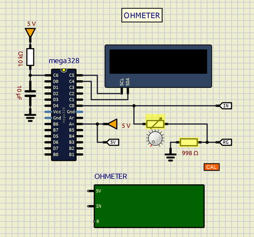
SCHEME:
The heart of the schematic is the ohmmeter subcircuit based on the ATmega328 Controller. It has three entrances:
IN: Sensitive input.
5V: Connected to +5v inside the subcircuit (Do not short circuit GND or connect to another voltage.
R: External point to adjust or control the calibration.
The subcircuit diagram is very simple and sufficiently self-explanatory. Add that the controller needs an object program (OHMETERH.hex) that by default is loaded in the controller and must always be loaded for it to work. The components in yellow are "exposer", a characteristic that has been attributed to them so that they can be modified from the outside as mentioned.
PROGRAM:
The program source is included in the subcircuit folder and is the same as other examples already published about this ohmmeter.
// OHMETER. DEFRAN23
// BASES: ARDUINO AND SIMULIDE TRUNK.

#include <Wire.h>
#include <Adafruit_GFX.h>
#include <Adafruit_SSD1306.h>
#define SCREEN_WIDTH 128
#define SCREEN_HEIGHT 32
#define OLED_RESET 4 // 4: Reset pin, 1 Arduino reset pin.
Adafruit_SSD1306 display(SCREEN_WIDTH, SCREEN_HEIGHT, &Wire, OLED_RESET);
float Rcal=1000;
float Rsample, Vana=0;

void setup()
{
display.begin(SSD1306_SWITCHCAPVCC, 0x3C); // Address 0x3C (60 DECIMAL)
display.display();
display.clearDisplay();
}

void loop()
{
int n=analogRead(A0);
Vana=map(n, 0,1024, 0,5000)/1000.0;
Rsample=(Rcal*(5.0-Vana))/Vana;
display.clearDisplay();
display.setTextSize(2);
display.setTextColor(WHITE);
display.setCursor(4, 0); // x,y
if (Rsample>1000)
{
Rsample=Rsample/1000.0;
display.print(Rsample);
display.setCursor(4, 18);
display.print("Kohms");
}
else
{
display.print(Rsample);
display.setCursor(4, 18);
display.print("Ohms");
}
display.display();
delay(100);
}
SUBCIRCUITS:
This example integrates several subcircuits located in the "data" folder into the ZIP attached. This folder must always be next to the "sim1" scheme so that it can be executed. A subcircuit is a “custom” circuit that accumulates a set of Simulide base components (primitive function) to obtain a new or an adapted function. These subcircuits are treated by Simulide as another component of its own structure. User can create his own subcircuits or use the ones published here in your own designs once the procedure is known, explained in detail in the Simulide tutorials: https://simulide.com/p/subcircuits/
* Communication with the author: Simulide/User/Messages/Defran
P. de Francisco.
Click for thumbs down.0Click for thumbs up.0
Last edited on March 17, 2024, 9:58 pm by Defran