
325__MEASURE A PULSE IN MILLISECONDS
Quote from Defran on January 23, 2024, 11:18 am
325_MEASURE A PULSE IN MILLISECONDS. (Simulide R2194 or higher)
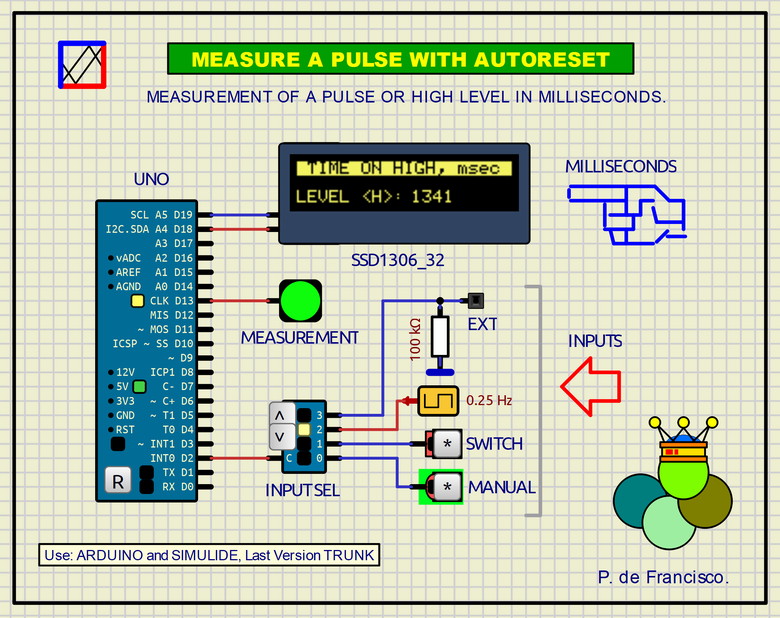
This example aims to measure the duration of a signal at a HIGH level in milliseconds. When the signal goes to a LOW level, the counter is reset. The value in milliseconds is displayed on the OLED dilpaly while a green LED lights up during this time. A four-position switch allows you to select between the following cases:
- Position 0: The measurement is made while the "MANUAL" button is pressed
- Position 1: The measurement is made while the switch is at HIGH level "SWITCH"
- Position 2: The measurement is made when the square signal of the oscillator is at a HIGH level.
- Position 3: It is an external INPUT.
SCHEME:
The scheme is very simple and is self-explanatory enough. An Arduino UNO is used as a controller and a 128x32 pixel OLED display communicated by I2C. The rest are standard components that are treated here as subcircuits to simplify the schematic.PROGRAM:
This is a C program for Arduino. Three standard libraries are used: Wire.h, Adafruit_GFX.h and Adafruit_SSD1306.h
// MEASURE A PULSE IN MILLISECONS. DEFRAN24 // BASES: ARDUINO AND SIMULIDE TRUNK. #include <Wire.h> #include <Adafruit_GFX.h> #include <Adafruit_SSD1306.h> Adafruit_SSD1306 display(128,32,&Wire,2,-1); // WIDTH, HEIGHT, WIRE, RST int pulsa=2; int mon=13; unsigned long time0; unsigned long time; void setup() { display.begin(SSD1306_SWITCHCAPVCC,0x3C); // Address 0x3C (60 DECIMAL) display.display(); display.clearDisplay(); pinMode(pulsa, INPUT_PULLUP); pinMode(mon, OUTPUT); time0=millis(); } void loop() { display.setTextSize(1); display.setTextColor(WHITE); display.setCursor(4, 4); // x,y display.setTextColor(BLACK, WHITE); display.print(" TIME ON HIGH, msec "); display.setTextColor(WHITE); display.display(); if (digitalRead(pulsa)) { digitalWrite(mon,HIGH); display.fillRect(4,20,60,30,BLACK); //DELETE: Xul,Yul,Xdr,Ydr, COLOR display.setCursor(4, 20); display.print("LEVEL <H>: "); time=millis()-time0; display.fillRect(61,20,127,30,BLACK); //DELETE: Xul,Yul,Xdr,Ydr, COLOR display.setCursor(68, 20); display.print(time); // MILLISECONDS } else { digitalWrite(mon,LOW); time0=millis(); display.fillRect(4,20,60,30,BLACK); //DELETE: Xul,Yul,Xdr,Ydr, COLOR display.setCursor(4, 20); display.print("LEVEL <L>: "); } }SUBCIRCUITS:This example integrates several subcircuits located in the "data" folder into the ZIP attached. This folder must always be next to the "sim1" scheme so that it can be executed. A subcircuit is a “custom” circuit that accumulates a set of Simulide base components (primitive function) to obtain a new or an adapted function. These subcircuits are treated by Simulide as another component of its own structure. User can create his own subcircuits or use the ones published here in your own designs once the procedure is known, explained in detail in the Simulide tutorials: https://simulide.com/p/subcircuits/* Communication with the author: Simulide/User/Messages/DefranP. de Francisco.
325_MEASURE A PULSE IN MILLISECONDS. (Simulide R2194 or higher)
This example aims to measure the duration of a signal at a HIGH level in milliseconds. When the signal goes to a LOW level, the counter is reset. The value in milliseconds is displayed on the OLED dilpaly while a green LED lights up during this time. A four-position switch allows you to select between the following cases:
- Position 0: The measurement is made while the "MANUAL" button is pressed
- Position 1: The measurement is made while the switch is at HIGH level "SWITCH"
- Position 2: The measurement is made when the square signal of the oscillator is at a HIGH level.
- Position 3: It is an external INPUT.
SCHEME:
PROGRAM:
This is a C program for Arduino. Three standard libraries are used: Wire.h, Adafruit_GFX.h and Adafruit_SSD1306.h
// MEASURE A PULSE IN MILLISECONS. DEFRAN24
// BASES: ARDUINO AND SIMULIDE TRUNK.

#include <Wire.h>
#include <Adafruit_GFX.h>
#include <Adafruit_SSD1306.h>
Adafruit_SSD1306 display(128,32,&Wire,2,-1); // WIDTH, HEIGHT, WIRE, RST
int pulsa=2;
int mon=13;
unsigned long time0;
unsigned long time;

void setup()
{
  display.begin(SSD1306_SWITCHCAPVCC,0x3C); // Address 0x3C (60 DECIMAL)
  display.display();
  display.clearDisplay();
  pinMode(pulsa, INPUT_PULLUP);
  pinMode(mon, OUTPUT);
  time0=millis();
}

void loop()
{
  display.setTextSize(1);
  display.setTextColor(WHITE);
  display.setCursor(4, 4);                 // x,y
  display.setTextColor(BLACK, WHITE);
  display.print(" TIME ON HIGH, msec ");
  display.setTextColor(WHITE);
  display.display();
  if (digitalRead(pulsa))
  {
    digitalWrite(mon,HIGH);
    display.fillRect(4,20,60,30,BLACK);   //DELETE: Xul,Yul,Xdr,Ydr, COLOR
    display.setCursor(4, 20);
    display.print("LEVEL <H>: ");
    time=millis()-time0;
    display.fillRect(61,20,127,30,BLACK);  //DELETE: Xul,Yul,Xdr,Ydr, COLOR
    display.setCursor(68, 20);
    display.print(time);                   // MILLISECONDS
  }
  else
  {
    digitalWrite(mon,LOW);
    time0=millis();
    display.fillRect(4,20,60,30,BLACK);   //DELETE: Xul,Yul,Xdr,Ydr, COLOR
    display.setCursor(4, 20);
    display.print("LEVEL <L>: ");
  }
}