Simulating Arduino Uno, Mega, and Nano in SimulIDE
SimulIDE supports the three most popular Arduino boards — Uno, Mega, and Nano — allowing you to write, compile, and test Arduino sketches against a simulated circuit before touching any physical hardware. All three boards share the same Arduino programming model, but they differ in pin count, memory, and peripheral set. Understanding these differences helps you choose the right board for your project and configure SimulIDE correctly.
This article covers how to set up the Arduino compiler, place each board, load firmware, and run a basic LED blink example on all three.
Prerequisites
This article assumes you are already familiar with:
- Placing components and wiring circuits in SimulIDE
- Starting and stopping the simulation
- Opening the code editor panel
If you need a refresher, check the SimulIDE Knowledge Base for the Basic Use and Circuit sections.
You should also have the Arduino IDE installed on your system (version 1.8.x recommended). SimulIDE uses the Arduino toolchain to compile sketches, so a working Arduino installation is required.
1. Arduino Boards in SimulIDE
SimulIDE provides three Arduino board components in the left panel under the microcontroller category:
| Feature | Arduino Uno | Arduino Nano | Arduino Mega |
|---|---|---|---|
| Microcontroller | ATmega328P | ATmega328P | ATmega2560 |
| Digital I/O Pins | 14 | 14 | 54 |
| PWM Pins | 6 | 6 | 15 |
| Analog Input Pins | 6 | 8 | 16 |
| Flash Memory | 32 KB | 32 KB | 256 KB |
| SRAM | 2 KB | 2 KB | 8 KB |
| EEPROM | 1 KB | 1 KB | 4 KB |
| UARTs | 1 | 1 | 4 |
| Clock Speed | 16 MHz | 16 MHz | 16 MHz |
| SimulIDE MCU ID | mega328 | mega328 | mega2560 |
The Uno and Nano share the same ATmega328P microcontroller, so they run the same compiled firmware and have identical pin behavior. The Nano simply has a more compact form factor and exposes 8 analog inputs instead of 6 (the extra two come from the ATmega328P’s ADC6 and ADC7, which are not available on the Uno board but are accessible on the Nano).
The Mega uses the ATmega2560, a significantly more capable chip with eight times the flash memory, four times the SRAM, and far more I/O pins. It also provides four hardware serial ports instead of one.
2. Configuring the Arduino Compiler
SimulIDE do support the Arduino compiler directly. You do not need to configure XML files or external toolchains manually. However, you must point SimulIDE to your Arduino IDE installation the first time you use it or if it changed.
And for every project you need to select the Board. By default Arduino UNo is used.

Setting the Tool Path
- Open an
.inofile in the SimulIDE code editor (right panel). - Click the Settings gear icon in the editor toolbar and select Compiler Settings.
- In the Arduino compiler row, click the button with three dots (
...) next to Tool Path. - Browse to your Arduino IDE installation folder.
Typical locations:
| Operating System | Arduino IDE 1.8.x Path |
|---|---|
| Windows | C:\Program Files (x86)\Arduino |
| Linux | /home/user/arduino-1.8.x |
| macOS | /Applications/Arduino.app |
If you are using Arduino IDE 2.x, the toolchain files may be in a different location. Check under your user data directory (e.g., ~/Arduino15/packages/arduino/tools/avr-gcc/) and point SimulIDE there.
Selecting the Board
In the same Compiler Settings dialog, choose the board that matches the component you will place in your circuit:
This selection determines which MCU definition and pin mapping the compiler uses. If you select the wrong board, the compiled firmware may not behave correctly on the simulated component.
3. Placing a Board and Loading Firmware
Finding the Boards
In the left component panel, expand the Microcontroller or Arduino category. You will find:
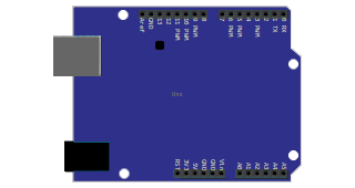
- Arduino Uno — standard form factor
- Arduino Nano — compact form factor
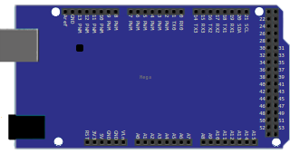
- Arduino Mega — large form factor with extra pin headers
Drag the board you need onto the circuit canvas and wire your circuit to its pins.
Loading Firmware
SimulIDE does not run .ino source files directly. It requires a compiled .hex firmware file. There are two ways to get this file into the simulated board.
Method 1: Compile inside SimulIDE
- Write or open your
.inosketch in the SimulIDE code editor. - Verify the compiler settings point to your Arduino IDE installation and the correct board is selected.
- Click the Compile button (checkmark icon) in the editor toolbar.
- If compilation succeeds, click the Upload button (down arrow icon) to load the firmware into the active MCU in the circuit.
Method 2: Load a pre-compiled HEX file
- Compile your sketch in the Arduino IDE using the same board selection.
- In the Arduino IDE, go to Sketch > Export Compiled Binary to generate a
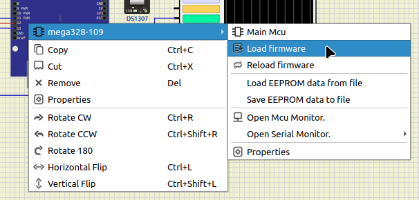
.hexfile in your sketch folder. - In SimulIDE, right-click on the Arduino board in the circuit.
- Select the MCU name from the submenu (e.g., mega328 for Uno/Nano, mega2560 for Mega).
- Click Load firmware and browse to the exported
.hexfile.
Auto-Reload on Simulation Start
To avoid manually reloading firmware every time you modify your sketch:
- Right-click the Arduino board in the circuit.
- Select the MCU name from the submenu (e.g., mega328 for Uno/Nano, mega2560 for Mega).
- Select Properties.
- Enable Reload HEX at Simulation Start.

With this option enabled, SimulIDE automatically loads the latest firmware each time you start the simulation, which is convenient during iterative development.
4. Example: LED Blink on All Three Boards
The classic Blink sketch turns the built-in LED (connected to pin 13) on and off at one-second intervals. This same sketch works on all three Arduino boards without modification.
The Sketch
void setup() {
    pinMode(LED_BUILTIN, OUTPUT);
}

void loop() {
    digitalWrite(LED_BUILTIN, HIGH);
    delay(1000);
    digitalWrite(LED_BUILTIN, LOW);
    delay(1000);
}
LED_BUILTIN is a constant defined by the Arduino core. It resolves to pin 13 on the Uno, Nano, and Mega.
Building the Circuit
For each board, the circuit is identical:
- Place the Arduino board on the canvas.
- Connect a resistor (220 to 330 ohms) between digital pin 13 and one terminal of an LED.
- Connect the other terminal of the LED to a GND pin on the board.
- Ensure the LED anode (positive side) is connected toward the resistor and the cathode (negative side) toward GND.
Running the Simulation
- Compile the sketch and upload it to the board (or load a pre-compiled
.hexfile). - Click the Power button to start the simulation.
- The LED should blink on and off at one-second intervals.
The simulation behaves identically across all three boards for this sketch. The difference only becomes apparent when you need more pins, more memory, or additional peripherals.
5. Choosing the Right Board
All three boards run the same Arduino sketches, so the choice depends on your project’s hardware requirements.
When to Use the Arduino Uno
- You are learning Arduino or prototyping a simple circuit.
- Your project uses a small number of sensors and actuators.
- Pin count and memory are not limiting factors.
- You want the most widely documented and supported board.
When to Use the Arduino Nano
- You need the same capabilities as the Uno in a smaller footprint.
- You are building a breadboard-friendly circuit.
- Your project will eventually fit in a compact enclosure.

The Nano’s 8 analog inputs (vs. 6 on the Uno) can be useful when you need to read a few more analog sensors without multiplexing.
When to Use the Arduino Mega
- Your project requires many digital I/O pins (more than 14).
- You need multiple hardware serial ports for communicating with several devices simultaneously.
- Your sketch uses large libraries, data tables, or buffers that exceed the Uno’s 2 KB SRAM.
- You are building a complex system such as a 3D printer controller, a multi-sensor data logger, or a robotics platform.
The Mega’s 256 KB of flash and 8 KB of SRAM give you room for large sketches that would not fit on the Uno or Nano.
6. Tips and Best Practices
- Board selection must match. The board chosen in the compiler settings must match the component placed in the circuit. Compiling for Arduino Uno and loading the firmware into an Arduino Mega will produce incorrect behavior.
- Keep sketch and hex together. Save your
.inosketch and the generated.hexfile in the same project folder. This makes it easier to manage firmware files and avoid loading stale builds. - Use Reload HEX at Simulation Start. Enable this property during development so you do not have to manually reload firmware after every code change.
- Verify pin numbers. Arduino pin numbers in your sketch correspond to the labeled pins on the SimulIDE board component, not the physical ATmega chip pin numbers. Use the board’s pin labels when wiring.
- Pin 13 caveat. On all three boards, pin 13 is connected to the built-in LED and also to the SCK pin of the SPI interface. If your project uses SPI, be aware that driving pin 13 as a general output may interfere with SPI communication.
- Use the Serial Monitor. Right-click the Arduino board and select Open Serial Monitor to view
Serial.print()output during simulation. This is invaluable for debugging sketches that do not produce visible output on LEDs or other components. - Use the MCU Monitor. Right-click the board and select Open MCU Monitor to watch registers, variables, RAM, and ROM in real time while the simulation is running.
7. Troubleshooting
| Problem | Likely Cause | Solution |
|---|---|---|
| Compile button does nothing | Compiler path not set or incorrect | Open Compiler Settings, verify the Tool Path points to your Arduino IDE folder |
| “Firmware successfully loaded” but LED does not blink | LED wiring reversed or wrong pin | Check LED polarity (anode toward pin 13, cathode toward GND) and verify pin number matches the sketch |
| Compilation errors about missing headers | Arduino board package not installed | Open Arduino IDE, go to Tools > Board > Boards Manager, and install “Arduino AVR Boards” |
| Serial Monitor shows nothing | Baud rate mismatch or sketch does not use Serial | Ensure your sketch calls Serial.begin(9600) (or matching baud) and the monitor is configured for the same rate |
| Simulation runs but board does not respond | Wrong MCU selected in compiler or firmware not loaded | Verify the compiler board selection matches the placed component; recompile and re-upload |
| Sketch works on Uno but not on Mega | Pin numbering differs between boards | Check the Mega’s pin mapping; some pins have different Arduino numbers than on the Uno |
| HEX file not found when loading firmware | File path contains spaces or special characters | Move your project to a simple path without spaces (e.g., C:\Arduino\Projects or /home/user/arduino) |
| Compilation works in Arduino IDE but fails in SimulIDE | SimulIDE points to a different Arduino installation | Recheck the Tool Path in Compiler Settings; it must point to the same installation used by the Arduino IDE |
8. Summary
| Feature | Arduino Uno | Arduino Nano | Arduino Mega |
|---|---|---|---|
| Microcontroller | ATmega328P | ATmega328P | ATmega2560 |
| Digital I/O | 14 | 14 | 54 |
| PWM | 6 | 6 | 15 |
| Analog Inputs | 6 | 8 | 16 |
| Flash | 32 KB | 32 KB | 256 KB |
| SRAM | 2 KB | 2 KB | 8 KB |
| Serial Ports | 1 | 1 | 4 |
| SimulIDE MCU ID | mega328 | mega328 | mega2560 |
| Best For | General prototyping | Compact projects | Complex, pin-heavy projects |
All three boards share the same Arduino programming model and the same SimulIDE workflow: place the board, wire the circuit, configure the compiler, compile the sketch, load the firmware, and hit play. The key difference is the underlying hardware capacity, which determines the scale of project each board can handle.