
probleme with control source
Quote from PrXavier on January 6, 2026, 5:45 pm
The current-controlled current source has a bug. The expected voltages are VA = 80 V, VB = −64 V, and VC = 156 V. This is not at all what the voltage probes are displaying.
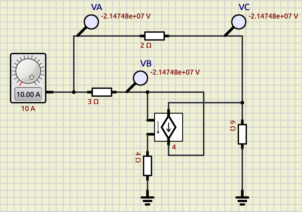
The current-controlled current source has a bug. The expected voltages are VA = 80 V, VB = −64 V, and VC = 156 V. This is not at all what the voltage probes are displaying.
Quote from arcachofo on January 7, 2026, 1:36 pmThis kind of circuits where you connect the "output" to the "input" will not work in this model.
In any case can you explain what do want to achieve with this circuit?
This kind of circuits where you connect the "output" to the "input" will not work in this model.
In any case can you explain what do want to achieve with this circuit?
Quote from PrXavier on January 7, 2026, 3:41 pm
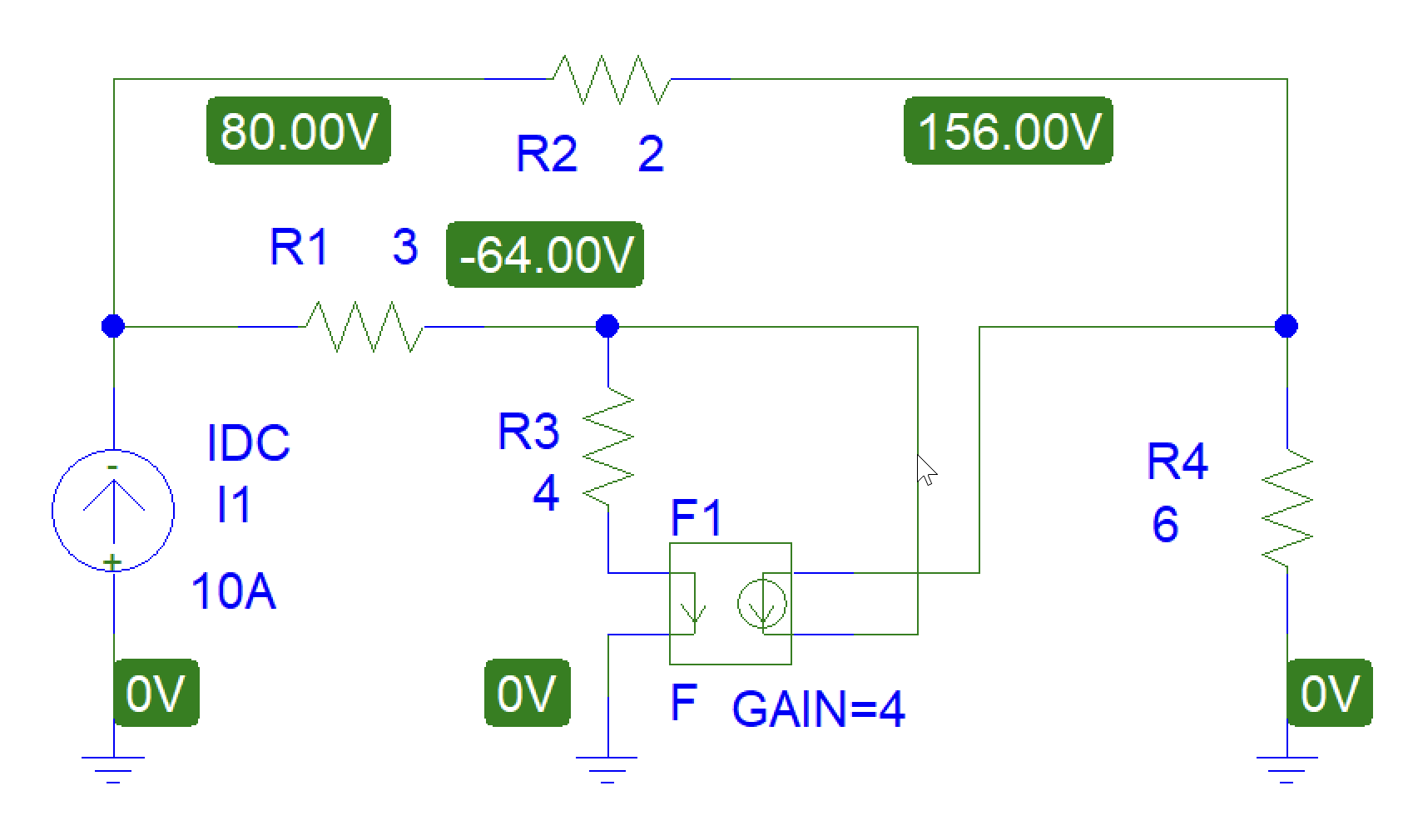
Hello, first of all thank you for your reply and for your responsiveness. This circuit is purely pedagogical and is intended to use a current-controlled current source. Typically, this is used in bipolar transistor models. The object of this exercise given to students is to calculate the voltages VA, VB, and VC. The demonstration is straightforward, and PSPICE displays the correct results.
In this circuit, the output is not connected to the input. The voltage VC can be considered as the output, but the purpose of this exercise is simply to determine the node potentials with a DC current source of 10 A. Obviously, the current and resistance values are not at all realistic for a real circuit; otherwise, things would heat up significantly. I modified the simulation parameters in SimulIde, but unsurprisingly this did not improve the situation.
Quote from arcachofo on January 7, 2026, 4:05 pmThanks for the explanations.
When I talk about "input" and "output" (quoted) I'm talking about the controlled source.
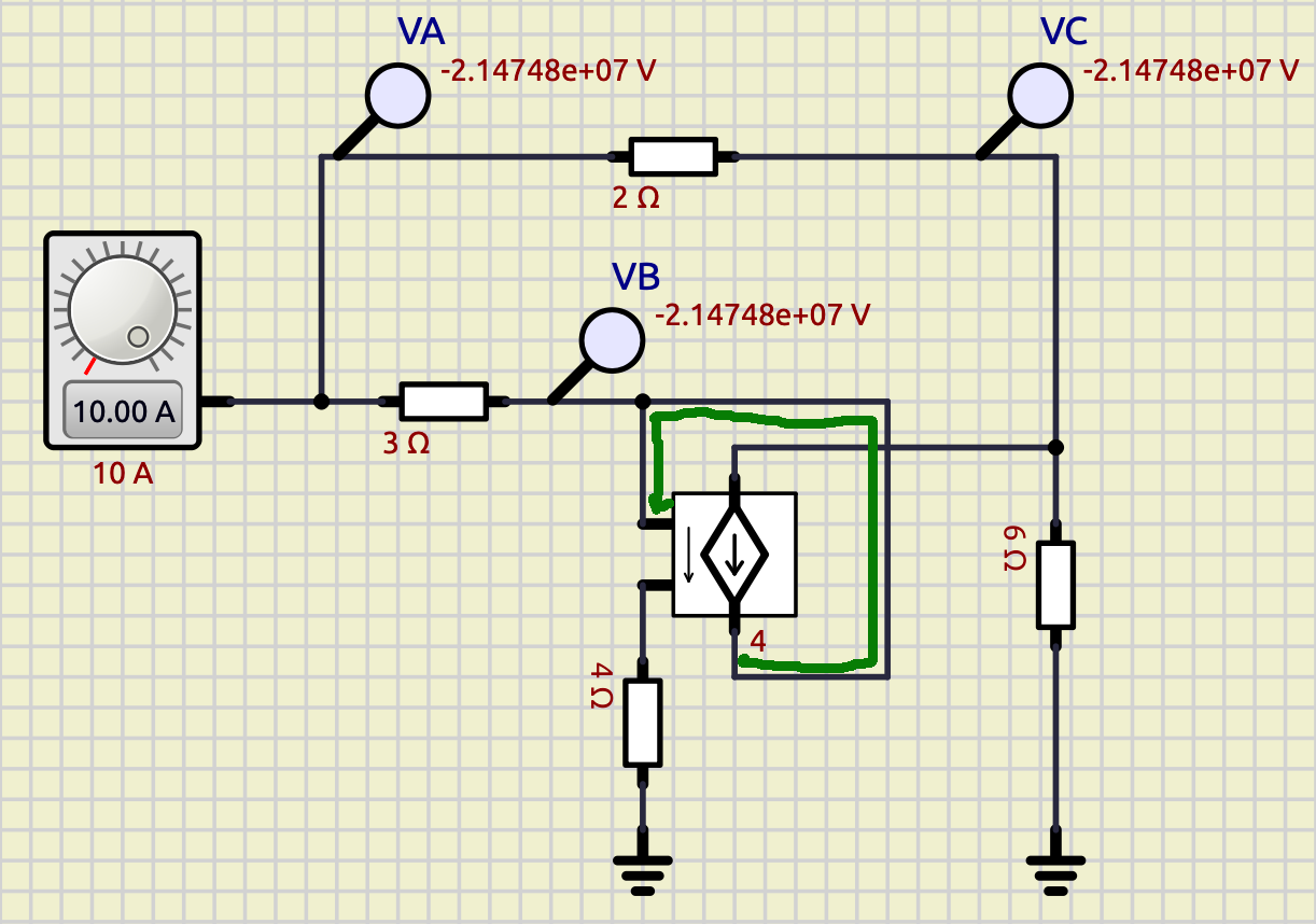
Input meaning the controlling current and Output meaning the controlled current.This will not work in this controlled source model:
Thanks for the explanations.
When I talk about "input" and "output" (quoted) I'm talking about the controlled source.
Input meaning the controlling current and Output meaning the controlled current.
This will not work in this controlled source model:
Quote from PrXavier on January 8, 2026, 1:07 am
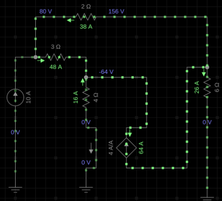
In fact, the problem does not come from the schematic, which is correct and whose simulation works with PSpice, EveryCircuit(this picture), and Proteus. The problem comes only with SimulIde.
The green line you drew is not correct. Indeed, since this is a controlled source, the two parts are independent in the circuit, because the power supply that allows the 64 A to be obtained is external.
It is not very easy to explain the concept of dependent sources in a few lines. Here, the gain of 4 makes it possible to go from 16 A to 64 A.
My schematic works with all the software, except SimulIde, so I conclude that there is perhaps an error in the program code. I have noticed other bugs in the software.
Are you a developer of the software? I could discuss another one with you at another time.
Quote from arcachofo on January 8, 2026, 3:31 amSeems that I can't explain myself very well.
I mean that the model for controlled source in SimulIDE does not work in this case.
It is a known limitation of this model.
Are you a developer of the software? I could discuss another one with you at another time.
Yes, I'm the developer and any bug report is very welcome.
Seems that I can't explain myself very well.
I mean that the model for controlled source in SimulIDE does not work in this case.
It is a known limitation of this model.
Are you a developer of the software? I could discuss another one with you at another time.
Yes, I'm the developer and any bug report is very welcome.