
PIC16 Comparator doesn't work
Quote from electr0n on September 23, 2025, 6:13 pmI installed the last build to try simulating the capacitor meter which I mentioned in my previous posts.
The program now runs, but the values shown on the display don't make sense even though the firmware is known to work in the real world.
I wonder how the comparator works when Vdd is not specified.
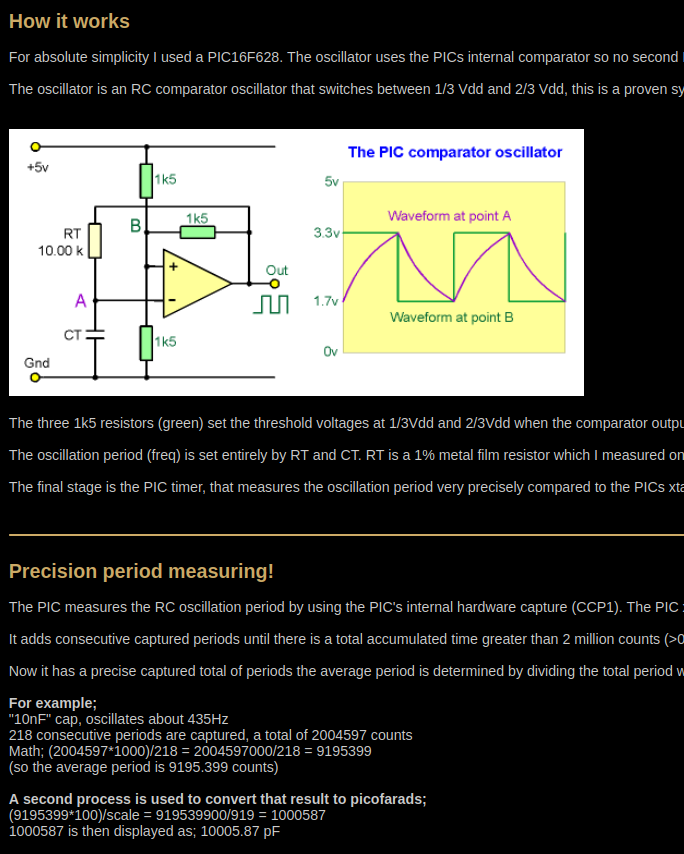
The author says on his site: The oscillator is an RC comparator oscillator that switches between 1/3 Vdd and 2/3 Vdd, this is a proven system and the frequency is reasonably unaffected by small changes in the 5v Vdd.
I am attaching the simulation files as usual, with minor updates (for visual aspect).
I installed the last build to try simulating the capacitor meter which I mentioned in my previous posts.
The program now runs, but the values shown on the display don't make sense even though the firmware is known to work in the real world.
I wonder how the comparator works when Vdd is not specified.
The author says on his site: The oscillator is an RC comparator oscillator that switches between 1/3 Vdd and 2/3 Vdd, this is a proven system and the frequency is reasonably unaffected by small changes in the 5v Vdd.
I am attaching the simulation files as usual, with minor updates (for visual aspect).
Quote from arcachofo on September 24, 2025, 1:23 pmYes, I noticed this issue, but the comparator is working ok.
The difference is in the expected frequency for certain capacitance.
For example The author says on his site:Another small cap example;
"100pF" osc about 43500 HzWhich is not correct.
And later:Mine reads about 320pF. The oscillator will be running about 220 kHz.
Which is correct.
But note that 100 pF oscillates at 43.5 kHz but a bigger 320 pF oscillates faster at 220 kHz ????
Something does not add up here...
Same thing for 10 nF:
"10nF" cap, oscillates about 435Hz
Which is not correct.
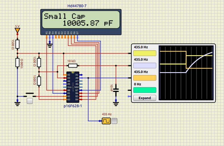
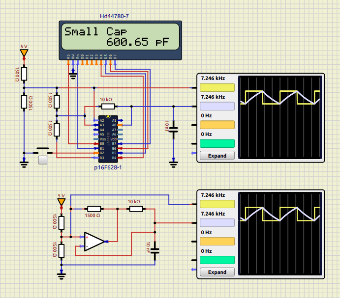
The real thing is that 10 nF doesn't oscillate at 435 Hz, but at aroud 7.2 kHz.If you feed 435 Hz directly to RA0 then you get 10000 pF in the LCD:
For me 10 nF oscillates at aroud 7.2 kHz. In the PIC circuit an also using an OpAmp.
I also confirmed it doing some calculations.
Yes, I noticed this issue, but the comparator is working ok.
The difference is in the expected frequency for certain capacitance.
For example The author says on his site:
Another small cap example;
"100pF" osc about 43500 Hz
Which is not correct.
And later:
Mine reads about 320pF. The oscillator will be running about 220 kHz.
Which is correct.
But note that 100 pF oscillates at 43.5 kHz but a bigger 320 pF oscillates faster at 220 kHz ????
Something does not add up here...
Same thing for 10 nF:
"10nF" cap, oscillates about 435Hz
Which is not correct.
The real thing is that 10 nF doesn't oscillate at 435 Hz, but at aroud 7.2 kHz.
If you feed 435 Hz directly to RA0 then you get 10000 pF in the LCD:
For me 10 nF oscillates at aroud 7.2 kHz. In the PIC circuit an also using an OpAmp.
I also confirmed it doing some calculations.
Quote from arcachofo on September 24, 2025, 2:24 pmHera are my calculations (which are consistent with the simulator) in case you want to check it, maybe you find some error:
The time to charge a capacitor from 1.67V to 3.33V in a series RC circuit with a 5V supply uses the standard RC charging relationship.
The formula for the time from 1.67V to 3.33V is:t = RC * ln( (5−1.67)/(5−3.33))
For the given values:
R = 10 kΩ = 10000 Ω
C = 10 nF = 10×10−9F
RC = 100 μsPlug the numbers into the formula:
t = 100 μs * ln(3.33/1.67)
t = 100 μs * ln(2)
t ≈ 100 μs * 0.693
t ≈ 69.3 μsSo the time required to charge from 1.67V to 3.33V is approximately 69 microseconds.
So it takes ~138.6 μs for a full cycle.
Which corresponds to a frequency of ~7215 Hz----------------------------------------------------------------------------------
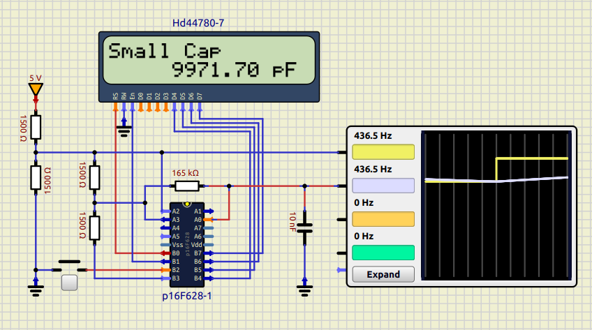
Using a 165 kΩ resistor instead of 10 kΩ seem to give results closer to expected.
Hera are my calculations (which are consistent with the simulator) in case you want to check it, maybe you find some error:
The time to charge a capacitor from 1.67V to 3.33V in a series RC circuit with a 5V supply uses the standard RC charging relationship.
The formula for the time from 1.67V to 3.33V is:
t = RC * ln( (5−1.67)/(5−3.33))
For the given values:
R = 10 kΩ = 10000 Ω
C = 10 nF = 10×10−9F
RC = 100 μs
Plug the numbers into the formula:
t = 100 μs * ln(3.33/1.67)
t = 100 μs * ln(2)
t ≈ 100 μs * 0.693
t ≈ 69.3 μs
So the time required to charge from 1.67V to 3.33V is approximately 69 microseconds.
So it takes ~138.6 μs for a full cycle.
Which corresponds to a frequency of ~7215 Hz
----------------------------------------------------------------------------------
Using a 165 kΩ resistor instead of 10 kΩ seem to give results closer to expected.
Quote from electr0n on September 24, 2025, 3:38 pmThanks a lot for taking the time to check and simulate the circuit.
If we consider the parasitic capacitance (roughly 320pF):R = 10 kΩ = 10000 Ω
C = 10.32 nF = 10.32×10⁻⁹F
RC = 103.2 μs
t = 103.2µs * ln(3.33/1.67)
t = 103.2µs * ln (2)
t = 71.53µsThus a whole cycle of 2 x 71.53µs corresoibds to 6990Hz.
What do you think ?
Thanks a lot for taking the time to check and simulate the circuit.
If we consider the parasitic capacitance (roughly 320pF):
R = 10 kΩ = 10000 Ω
C = 10.32 nF = 10.32×10⁻⁹F
RC = 103.2 μs
t = 103.2µs * ln(3.33/1.67)
t = 103.2µs * ln (2)
t = 71.53µs
Thus a whole cycle of 2 x 71.53µs corresoibds to 6990Hz.
What do you think ?
Quote from arcachofo on September 24, 2025, 3:46 pmThe PIC is powered by 5V in the real world, so I'm not sure that you can consider 3.3V in your frequency calculations.
3.3V is 2/3 of 5V:
The oscillator is an RC comparator oscillator that switches between 1/3 Vdd and 2/3 Vdd
EDIT:
In any case in your calculations you get around 4418 Hz, not 435 Hz
The PIC is powered by 5V in the real world, so I'm not sure that you can consider 3.3V in your frequency calculations.
3.3V is 2/3 of 5V:
The oscillator is an RC comparator oscillator that switches between 1/3 Vdd and 2/3 Vdd
EDIT:
In any case in your calculations you get around 4418 Hz, not 435 Hz
Quote from electr0n on September 24, 2025, 3:56 pmOk never mind 🙂
I edited my previous post but end up with a different frequency if we consider the parasitic capacitance and the 270pF. This is not negligible, but still doesn't explain why we don't get the accurate values as with the real circuit.
Ok never mind 🙂
I edited my previous post but end up with a different frequency if we consider the parasitic capacitance and the 270pF. This is not negligible, but still doesn't explain why we don't get the accurate values as with the real circuit.
Quote from arcachofo on September 24, 2025, 4:08 pmQuote from electr0n on September 24, 2025, 3:56 pmOk never mind 🙂
I edited my previous post but end up with a different frequency if we consider the parasitic capacitance and the 270pF. This is not negligible, but still doesn't explain why we don't get the accurate values as with the real circuit.
That is still far from 435 Hz:
For example;
"10nF" cap, oscillates about 435Hz
Quote from electr0n on September 24, 2025, 3:56 pmOk never mind 🙂
I edited my previous post but end up with a different frequency if we consider the parasitic capacitance and the 270pF. This is not negligible, but still doesn't explain why we don't get the accurate values as with the real circuit.
That is still far from 435 Hz:
For example;
"10nF" cap, oscillates about 435Hz
Quote from arcachofo on September 24, 2025, 4:14 pmI don't know what is the problem, maybe different versions of circuit and/or firmware, but this firmware doesn't work with that circuit.
To get 435 Hz you need around 165 kΩ, not 10 kΩ.
I don't know what is the problem, maybe different versions of circuit and/or firmware, but this firmware doesn't work with that circuit.
To get 435 Hz you need around 165 kΩ, not 10 kΩ.
Quote from arcachofo on September 24, 2025, 5:49 pmJust to define what is exactly the problem:
It must be some kind of error here, that circuit does NOT oscillate at 435 Hz:
And it is obvious:
At 435 Hz the rise time is over 1ms.
RC time constant for 10kΩ and 10 nF is 100 µs (0 to 63.2% V).
So 33% to 66% must be below 100 µs (69 µs indeed)
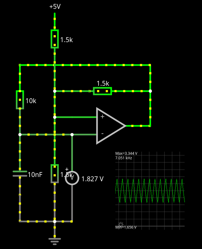
You don't even need to do calculations, the circuit below should oscillate at several kHz, not 435 Hz:
Also tested with Falstad Simulator just in case.
And obviously it oscillates at around 7 kHz
Just to define what is exactly the problem:
It must be some kind of error here, that circuit does NOT oscillate at 435 Hz:
And it is obvious:
At 435 Hz the rise time is over 1ms.
RC time constant for 10kΩ and 10 nF is 100 µs (0 to 63.2% V).
So 33% to 66% must be below 100 µs (69 µs indeed)
You don't even need to do calculations, the circuit below should oscillate at several kHz, not 435 Hz:
Also tested with Falstad Simulator just in case.
And obviously it oscillates at around 7 kHz
Quote from electr0n on September 24, 2025, 7:57 pmCheck this interesting discussion around the comparator operaiton in this circuit. Apparently the comparator has a 300ns propagation delay.
The ASM source code is even given there, so the code can be inspected.
Check this interesting discussion around the comparator operaiton in this circuit. Apparently the comparator has a 300ns propagation delay.
The ASM source code is even given there, so the code can be inspected.