New subcircuits for SimulIDE (v. 1.1.0 and higher)
Quote from Fizik_S on December 10, 2023, 9:50 amI propose 3 new subcircuits for the simulator.
ACS712.05 linear current sensor ACS712 (5 A version)
ACS712.20 linear current sensor ACS712 (20 A version)
ACS712.30 linear current sensor ACS712 (30 A version)Help files with basic characteristics (in Russian) have been made for subcircuits.
Installation:
Extract the contents of the archive to the directory with the installed program and add it to the file unsorted.xml lines:<item name="ACS712.05" info="5A Linear Current Sensor" /> <item name="ACS712.20" info="20A Linear Current Sensor" /> <item name="ACS712.30" info="30A Linear Current Sensor" />The subcircuits are designed for the program version R2068 and higher.
I propose 3 new subcircuits for the simulator.
ACS712.05 linear current sensor ACS712 (5 A version)
ACS712.20 linear current sensor ACS712 (20 A version)
ACS712.30 linear current sensor ACS712 (30 A version)
Help files with basic characteristics (in Russian) have been made for subcircuits.
Installation:
Extract the contents of the archive to the directory with the installed program and add it to the file unsorted.xml lines:
  <item name="ACS712.05" info="5A Linear Current Sensor" />
  <item name="ACS712.20" info="20A Linear Current Sensor" />
  <item name="ACS712.30" info="30A Linear Current Sensor" />
The subcircuits are designed for the program version R2068 and higher.
Quote from Fizik_S on January 14, 2024, 9:02 amI bring to your attention a few more subcircuits of current sensors:
ACS723.05AB - current sensor +/- 5 A
ACS723.10AB - current sensor +/- 10 A
ACS723.10AU - 10 A current sensor
ACS723.20AB - current sensor +/- 20 A
ACS723.20AU - 20 A current sensor
ACS723.40AB - current sensor +/- 40 A
ACS723.40AU - 40 A current sensor
ACS723.50AB - current sensor +/- 50 AThe subcircuits are simplified: the contact BW_S of the microcircuit is not simulated.
The archive also contains help files for each subcircuit (Russian).The subcircuits will only work in the program SimulIDE 1.1.0 Rev2068 and above
Installation:
Unpack the contents of the archive into the directory with the installed program, add to the file unsorted.xml the following lines:<item name="ACS723.05AB" info="5A Linear Bipolar Current Sensor" />
<item name="ACS723.10AU" info="10A Linear Unipolar Current Sensor" />
<item name="ACS723.10AB" info="10A Linear Bipolar Current Sensor" />
<item name="ACS723.20AU" info="20A Linear Unipolar Current Sensor" />
<item name="ACS723.20AB" info="20A Linear Bipolar Current Sensor" />
<item name="ACS723.40AU" info="40A Linear Unipolar Current Sensor" />
<item name="ACS723.40AB" info="40A Linear Bipolar Current Sensor" />
<item name="ACS723.50AB" info="50A Linear Bipolar Current Sensor" />
I bring to your attention a few more subcircuits of current sensors:
ACS723.05AB - current sensor +/- 5 A
ACS723.10AB - current sensor +/- 10 A
ACS723.10AU - 10 A current sensor
ACS723.20AB - current sensor +/- 20 A
ACS723.20AU - 20 A current sensor
ACS723.40AB - current sensor +/- 40 A
ACS723.40AU - 40 A current sensor
ACS723.50AB - current sensor +/- 50 A
The subcircuits are simplified: the contact BW_S of the microcircuit is not simulated.
The archive also contains help files for each subcircuit (Russian).
The subcircuits will only work in the program SimulIDE 1.1.0 Rev2068 and above
Installation:
Unpack the contents of the archive into the directory with the installed program, add to the file unsorted.xml the following lines:
<item name="ACS723.05AB" info="5A Linear Bipolar Current Sensor" />
<item name="ACS723.10AU" info="10A Linear Unipolar Current Sensor" />
<item name="ACS723.10AB" info="10A Linear Bipolar Current Sensor" />
<item name="ACS723.20AU" info="20A Linear Unipolar Current Sensor" />
<item name="ACS723.20AB" info="20A Linear Bipolar Current Sensor" />
<item name="ACS723.40AU" info="40A Linear Unipolar Current Sensor" />
<item name="ACS723.40AB" info="40A Linear Bipolar Current Sensor" />
<item name="ACS723.50AB" info="50A Linear Bipolar Current Sensor" />
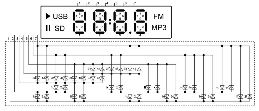
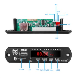
Quote from Fizik_S on November 14, 2024, 2:11 pmI propose a model of the LED display used in Chinese media players.
he feature of the display is the connection of LEDs using the Charliplexing method.
Installation: Unpack the contents of the archive to the directory "..\data\led_display\" of the simulator, add to the file "led_display.xml " a line:
<item name="4bit_fm_mp3" info="4-Bit Led Display, Charlieplexing LEDs" />
I propose a model of the LED display used in Chinese media players.
he feature of the display is the connection of LEDs using the Charliplexing method.
Installation: Unpack the contents of the archive to the directory "..\data\led_display\" of the simulator, add to the file "led_display.xml " a line:
<item name="4bit_fm_mp3" info="4-Bit Led Display, Charlieplexing LEDs" />


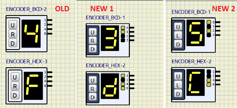
Quote from Fizik_S on November 27, 2024, 9:51 pmI suggest slightly modified tools: ENCODER_BCD and ENCODER_HEX.
There are 2 catalogs in the attached archive: [1] and [2] with modified subcircuits.
The catalog [1] contains encoders with the following modifications:
1) Automatic reset to 0 when starting the simulation.
2) Added a binary code indicator at the encoder output.
The appearance of the encoder in the screenshot marked <NEW1>The catalog [2] contains encoders with the following modifications:
1) Automatic reset to 0 when starting the simulation.
2) Added a binary code indicator at the encoder output.
3) The <L> (Load) button loads the code that was on the indicator before turning off the simulation.4) The encoders retain their state when the circuit is saved.
The appearance of the encoder in the screenshot marked <NEW2>
These encoders remember the last entered code.Installation: Copy the contents of one of the directories [1] or [2] from the attached archive to the "...\data\tools\" directory of the simulator with file replacement.
The encoders are tested in simulator version 1.2.0 RC1
I suggest slightly modified tools: ENCODER_BCD and ENCODER_HEX.
There are 2 catalogs in the attached archive: [1] and [2] with modified subcircuits.
The catalog [1] contains encoders with the following modifications:
1) Automatic reset to 0 when starting the simulation.
2) Added a binary code indicator at the encoder output.
The appearance of the encoder in the screenshot marked <NEW1>
The catalog [2] contains encoders with the following modifications:
1) Automatic reset to 0 when starting the simulation.
2) Added a binary code indicator at the encoder output.
3) The <L> (Load) button loads the code that was on the indicator before turning off the simulation.
4) The encoders retain their state when the circuit is saved.
The appearance of the encoder in the screenshot marked <NEW2>
These encoders remember the last entered code.
Installation: Copy the contents of one of the directories [1] or [2] from the attached archive to the "...\data\tools\" directory of the simulator with file replacement.
The encoders are tested in simulator version 1.2.0 RC1

Quote from KerimF on November 28, 2024, 7:43 amHi,
Your solution of adding the 'Load' button and saving the last status is great indeed. It saves a lot of time while debugging a newly written code that needs your encoders.
Wishing you the best.
Kerim
Hi,
Your solution of adding the 'Load' button and saving the last status is great indeed. It saves a lot of time while debugging a newly written code that needs your encoders.
Wishing you the best.
Kerim
Quote from Fizik_S on June 25, 2025, 8:14 amWhile creating models for Proteus Pro, I came across a curious artifact of the past: a behavioral model for the i8255 built on logical primitives. I decided to adapt it for SimulIDE. I'm sharing the result.
The subcircuit simulates the operation of the PPI i8255 in mode 0 (simple parallel input or output). This is sufficient for most tasks.The subcircuit is designed for SimulIDE 1.2.0. It will not work in earlier versions.
Please test it and point out any errors.Installation:
Extract the contents of the archive to the directory SimulIDE_1.2.0-xxx\data\ICs\
To the file unsorted.xml add a line:<item name="i8255" info="Programmable Peripheral Interface (PPI)" />
While creating models for Proteus Pro, I came across a curious artifact of the past: a behavioral model for the i8255 built on logical primitives. I decided to adapt it for SimulIDE. I'm sharing the result.
The subcircuit simulates the operation of the PPI i8255 in mode 0 (simple parallel input or output). This is sufficient for most tasks.
The subcircuit is designed for SimulIDE 1.2.0. It will not work in earlier versions.
Please test it and point out any errors.
Installation:
Extract the contents of the archive to the directory SimulIDE_1.2.0-xxx\data\ICs\
To the file unsorted.xml add a line:
<item name="i8255" info="Programmable Peripheral Interface (PPI)" />
