
keypad with diodes
Quote from beep_doop on June 15, 2024, 3:45 pmHi all,
it would be really useful to have a keypad with builtin diodes, to acurately read multiple simultaniously pressed buttons.
i tried implementing this myself by modifying the code for the keypad,
but somehow can't get the buttons to connect to the diodes.void KeyPad_with_Diodes::setupButtons() { //... button->SetupButton(); button->setParentItem( this ); button->setPos( QPointF(col*16+12, 16+row*16 ) ); button->setFlag( QGraphicsItem::ItemIsSelectable, false ); m_buttons.append( button ); QString dioId = m_id+"diode"+QString::number(row)+QString::number(col); eDiode* diode = new eDiode (dioId); diode->setModel( "Diode Default" ); m_diodes.append( diode ); //... }now the diodes seem to work fine, i can connect them directly to the input and output pins to create a grid of just diodes:
void KeyPad_with_Diodes::stamp() { for( int row=0; row<m_rows; row++ ) { Pin* rowPin = m_pin[row]; for( int col=0; col<m_cols; col++ ) { Pin* colPin = m_pin[m_rows+col]; eDiode* diode = m_diodes.at( row*m_cols+col ); diode->setEpin( 0, rowPin ); diode->setEpin(1,colPin); } } }now trying to connect the rowpin -> diode -> button -> colpin:
void KeyPad_with_Diodes::stamp() { for( int row=0; row<m_rows; row++ ) { Pin* rowPin = m_pin[row]; for( int col=0; col<m_cols; col++ ) { Pin* colPin = m_pin[m_rows+col]; eNode* colNode = colPin->getEnode(); PushBase* button = m_buttons.at( row*m_cols+col ); eDiode* diode = m_diodes.at( row*m_cols+col ); diode->setEpin( 0, rowPin ); ePin* buttonEpin0 = button->getEpin( 0 ); diode->setEpin(1,buttonEpin0); ePin* buttonEpin1 = button->getEpin( 1 ); buttonEpin1->setEnode( colNode ); } } }now there's no current flowing at all in either direction buttons pressed or not.
what's the correct way to connect these, please help
Hi all,
it would be really useful to have a keypad with builtin diodes, to acurately read multiple simultaniously pressed buttons.
i tried implementing this myself by modifying the code for the keypad,
but somehow can't get the buttons to connect to the diodes.
void KeyPad_with_Diodes::setupButtons()
{
//...
   button->SetupButton();
   button->setParentItem( this );
   button->setPos( QPointF(col*16+12, 16+row*16 ) );
   button->setFlag( QGraphicsItem::ItemIsSelectable, false );
   m_buttons.append( button );

   QString dioId = m_id+"diode"+QString::number(row)+QString::number(col);
   eDiode* diode = new eDiode (dioId);
   diode->setModel( "Diode Default" );
   m_diodes.append( diode );
//...
}
now the diodes seem to work fine, i can connect them directly to the input and output pins to create a grid of just diodes:
 void KeyPad_with_Diodes::stamp()
 {
     for( int row=0; row<m_rows; row++ )
     {
         Pin* rowPin = m_pin[row];
         for( int col=0; col<m_cols; col++ )
         {
             Pin* colPin = m_pin[m_rows+col];
             eDiode* diode = m_diodes.at( row*m_cols+col );
             diode->setEpin( 0, rowPin );
             diode->setEpin(1,colPin);
	 }
     }
}
now trying to connect the rowpin -> diode -> button -> colpin:
void KeyPad_with_Diodes::stamp()
{
  for( int row=0; row<m_rows; row++ )
  {
    Pin* rowPin = m_pin[row];
    for( int col=0; col<m_cols; col++ )
    {
      Pin* colPin = m_pin[m_rows+col];
      eNode* colNode = colPin->getEnode();

      PushBase* button = m_buttons.at( row*m_cols+col );

      eDiode* diode = m_diodes.at( row*m_cols+col );
      diode->setEpin( 0, rowPin );

      ePin* buttonEpin0 = button->getEpin( 0 );
      diode->setEpin(1,buttonEpin0);

      ePin* buttonEpin1 = button->getEpin( 1 );
      buttonEpin1->setEnode( colNode );
    }
  }
}
now there's no current flowing at all in either direction buttons pressed or not.
what's the correct way to connect these, please help
Quote from arcachofo on June 15, 2024, 4:08 pmHi, the best way to make a keypad with diodes is creating a subcircuit.
You can find an example of keyboard subcircuit in File_exploerer->Examples->Micro->Z80->ZX_Spectrum
In "data" folder have a look at ZX_keyboard.
Hi, the best way to make a keypad with diodes is creating a subcircuit.
You can find an example of keyboard subcircuit in File_exploerer->Examples->Micro->Z80->ZX_Spectrum
In "data" folder have a look at ZX_keyboard.
Quote from beep_doop on June 15, 2024, 4:58 pmHi,
I don't think Subcircuits work for this.
I want an Element that is as configurable as a keypad (arbitrary number of columns and rows and arbitrary keylayout)
while having a diode in front of every button.is this really achievable with subcircuits ?
Hi,
I don't think Subcircuits work for this.
I want an Element that is as configurable as a keypad (arbitrary number of columns and rows and arbitrary keylayout)
while having a diode in front of every button.
is this really achievable with subcircuits ?
Quote from arcachofo on June 15, 2024, 5:16 pmQuote from beep_doop on June 15, 2024, 4:58 pmHi,
I don't think Subcircuits work for this.
I want an Element that is as configurable as a keypad (arbitrary number of columns and rows and arbitrary keylayout)
while having a diode in front of every button.is this really achievable with subcircuits ?
Ok, then to make your code work, you need an internal enode for each button.
Let me see if there is some component you can use as example...
Quote from beep_doop on June 15, 2024, 4:58 pmHi,
I don't think Subcircuits work for this.
I want an Element that is as configurable as a keypad (arbitrary number of columns and rows and arbitrary keylayout)
while having a diode in front of every button.is this really achievable with subcircuits ?
Ok, then to make your code work, you need an internal enode for each button.
Let me see if there is some component you can use as example...
Quote from arcachofo on June 15, 2024, 5:42 pmFor example you can have a look at src/gui/circuitwidget/components/active/diac.cpp
But there are some other things to do, I think this should be enough:
- After creating each eDiode, call: diode->setNumEpins( 2 );
This creates ePins for the diode.- Add KeyPad_with_Diodes::initialize()
Here you must create an eNode for each diode (see diac.cpp)
This eNode is the connection point between button and diode.- In KeyPad_with_Diodes::stamp() do the connections:
dNodeXX is the eNode created in KeyPad_with_Diodes::initialize() (same index as diode)ePin* buttonEpin0 = button->getEpin( 0 ); ePin* buttonEpin1 = button->getEpin( 1 ); ePin* diodeEpin0 = diode->getEpin( 0 ); // Anode ePin* diodeEpin1 = diode->getEpin( 1 ); // Cathode buttonEpin0->setEnode( rowNode ); buttonEpin1->setEnode( dNodeXX ); diodeEpin0->setEnode( dNodeXX ); diodeEpin1->setEnode( colNode );
For example you can have a look at src/gui/circuitwidget/components/active/diac.cpp
But there are some other things to do, I think this should be enough:
- After creating each eDiode, call: diode->setNumEpins( 2 );
This creates ePins for the diode.
- Add KeyPad_with_Diodes::initialize()
Here you must create an eNode for each diode (see diac.cpp)
This eNode is the connection point between button and diode.
- In KeyPad_with_Diodes::stamp() do the connections:
dNodeXX is the eNode created in KeyPad_with_Diodes::initialize() (same index as diode)
ePin* buttonEpin0 = button->getEpin( 0 );
ePin* buttonEpin1 = button->getEpin( 1 );

ePin* diodeEpin0 = diode->getEpin( 0 ); // Anode
ePin* diodeEpin1 = diode->getEpin( 1 ); // Cathode

buttonEpin0->setEnode( rowNode );
buttonEpin1->setEnode( dNodeXX );
diodeEpin0->setEnode( dNodeXX );
diodeEpin1->setEnode( colNode );
Quote from beep_doop on June 15, 2024, 6:41 pmyaay it works, thanks a lot !! :),
shall I send a PR ? (after some more testing)
yaay it works, thanks a lot !! :),
shall I send a PR ? (after some more testing)
Quote from arcachofo on June 16, 2024, 12:17 pmGlad to know you got it working.
shall I send a PR ? (after some more testing)
Keypad with diodes can be useful, but I think it could be an option for the existing keypad.
This can be done by adding a boolean property "Add Diodes" or whatever.
Then the creation of eNodes and eDiodes as well as the connections should be conditional to the value of the property.
Changing this property should stop the simulation: have a look at KeyPad::setupButtons() (or just set the value and call setupButtons() to remake everything again).As an example of boolean property you can have a look at property "Normally Closed" in push.cpp (for example).
I haven't seen the complete code, but just in case: eDiodes should be deleted at KeyPad::setupButtons() (same than butons), and KeyPad::remove()
Glad to know you got it working.
shall I send a PR ? (after some more testing)
Keypad with diodes can be useful, but I think it could be an option for the existing keypad.
This can be done by adding a boolean property "Add Diodes" or whatever.
Then the creation of eNodes and eDiodes as well as the connections should be conditional to the value of the property.
Changing this property should stop the simulation: have a look at KeyPad::setupButtons() (or just set the value and call setupButtons() to remake everything again).
As an example of boolean property you can have a look at property "Normally Closed" in push.cpp (for example).
I haven't seen the complete code, but just in case: eDiodes should be deleted at KeyPad::setupButtons() (same than butons), and KeyPad::remove()
Quote from beep_doop on June 17, 2024, 10:41 pmI think it's done now
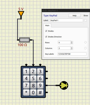
I have added two boolean properties, one for adding diodes and one for the polarity of the diodes
I am deleting the diodes but not the eNodes, when I try that i get segfaults, seems like they get deleted elsewhere already ?I also changed setupButtons() to only delete and add the peripheral pins if necessary to not destroy external wiring on every change.
void KeyPad::setupButtons(int prev_rows, int prev_cols)
{
//...
for (int col = m_cols; col < prev_cols; col ++ )
{
    deletePin(m_pin.end()[-1]);
    m_pin.pop_back();
}
if (prev_rows > m_rows)
{
    for (int row = m_rows; row < prev_rows; row ++ )deletePin(m_pin[row]);
    m_pin.erase(m_pin.begin()+m_rows,m_pin.begin()+prev_rows);
}
m_pin.resize( m_rows + m_cols );

int n_added_rows=m_rows-prev_rows;
if (n_added_rows > 0 )
        for (int i = m_pin.size()-1; i >= m_pin.size()-m_cols;i--)
{
    m_pin[i] = m_pin[i-n_added_rows];
}
//...
}
it seems to work very well.
I think it's done now
I have added two boolean properties, one for adding diodes and one for the polarity of the diodes
I am deleting the diodes but not the eNodes, when I try that i get segfaults, seems like they get deleted elsewhere already ?
I also changed setupButtons() to only delete and add the peripheral pins if necessary to not destroy external wiring on every change.
void KeyPad::setupButtons(int prev_rows, int prev_cols)
{
//...
for (int col = m_cols; col < prev_cols; col ++ )
{
    deletePin(m_pin.end()[-1]);
    m_pin.pop_back();
}
if (prev_rows > m_rows)
{
    for (int row = m_rows; row < prev_rows; row ++ )deletePin(m_pin[row]);
    m_pin.erase(m_pin.begin()+m_rows,m_pin.begin()+prev_rows);
}
m_pin.resize( m_rows + m_cols );

int n_added_rows=m_rows-prev_rows;
if (n_added_rows > 0 )
        for (int i = m_pin.size()-1; i >= m_pin.size()-m_cols;i--)
{
    m_pin[i] = m_pin[i-n_added_rows];
}
//...
}
it seems to work very well.
Uploaded files:Quote from arcachofo on June 18, 2024, 9:56 amGreat!
Yes it is working for me as well.I am deleting the diodes but not the eNodes, when I try that i get segfaults, seems like they get deleted elsewhere already ?
Yes, eNodes are created (and deleted) at every simulation run.
I also changed setupButtons() to only delete and add the peripheral pins if necessary to not destroy external wiring on every change.
Nice, that's a good improvement.
The only thing I see is that "Diodes Direction" does not make clear which direction.
Maybe something like "Anode to Row" or similar would be more informative of what is actually happening.Feel free to do a PR if you want.
Great!
Yes it is working for me as well.
I am deleting the diodes but not the eNodes, when I try that i get segfaults, seems like they get deleted elsewhere already ?
Yes, eNodes are created (and deleted) at every simulation run.
I also changed setupButtons() to only delete and add the peripheral pins if necessary to not destroy external wiring on every change.
Nice, that's a good improvement.
The only thing I see is that "Diodes Direction" does not make clear which direction.
Maybe something like "Anode to Row" or similar would be more informative of what is actually happening.
Feel free to do a PR if you want.
Quote from beep_doop on June 18, 2024, 6:33 pmI kept the name but added arrows to the pins to show the polarity.
works flipped and rotated and in both polarities
i sent a pull request
I kept the name but added arrows to the pins to show the polarity.
works flipped and rotated and in both polarities
i sent a pull request